Built in office furniture
Introduction
This article gives an illustration of how to build some bespoke furniture. In this case it was intended for use in a home office or study, but the principles would work equally well in other locations.
(click the photos for larger sizes)
Design
The design goal here was to take an office that is too small, and full of too much stuff, and better organise it! One of the key problems was the rear corner. In an alcove beside a chimney breast, there was a tatty old cupboard, and a 4 drawer filing cabinet, with a few shelves above. In front of that was another tatty cabinet, and a spare kitchen cabinet fixed to the wall above it that had been found in the garage when we moved in, and pressed into service to add some more storage space. The end result was a bit of a mess, and not at all easy to get at.
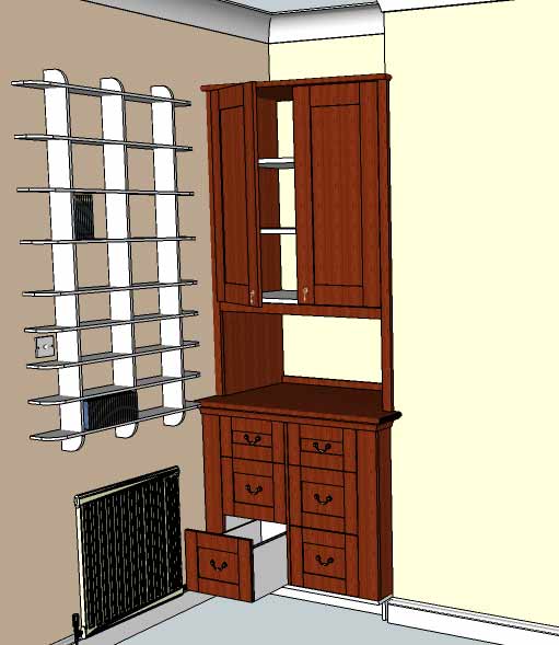
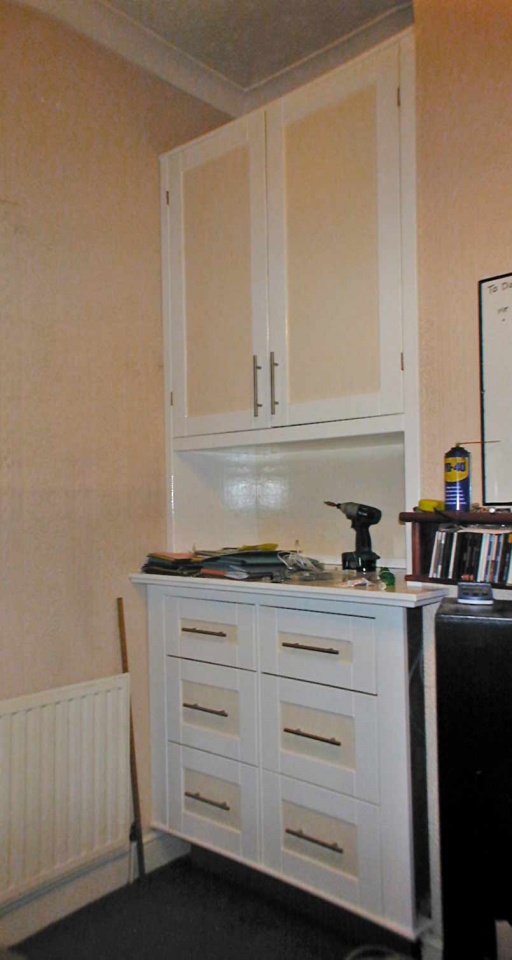
So the design was approached with the obligatory sketchup model (see above). It was to have 4 filing drawers to replace the metal filing cabinet, plus a couple more decent sized drawers for "stuff". Above this was to be a cupboard unit, but lifted clear of the top of the base unit, to provide some workspace big enough to hold a computer or monitor or other similar sized kit. The cupboard space was intended to be substantial, and take the total combined height to around 9' tall! The unit was to fill the total width of the alcove at around 3'6".
The first design was conceived as a hardwood, French polished affair. However that was soon rejected on the grounds that it would not suite the location particularly well, and the cost of the materials would be rather steep, for what after all, is in an office! So a softwood / ply / and painted finish was adopted instead...
Materials
2 sheets of 18mm WBP ply, 2 sheets of 12mm ply, 1 sheet 6mm MDF, 1 sheet 6mm ply, 1/2 Sheet of 18mm MDF, 4 of 2.4m lengths of 9"x1" PAR softwood, 1 2m length of 7 x 3/4" PAR, six heavy duty drawer runners (ebay), and handles & hinges etc.
Construction
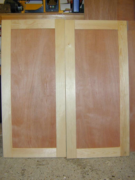
The drawers and cupboard doors are both built using the same technique. A face frame is made up from 3" / 75mm softwood rails and stiles, and the inset panel is simply 6mm ply.
Drawers
The drawers were the first thing that deviated from the original design a little. Since it was felt that the filing cabinet ones would need decent substantial runners to work well, a set of three part full extension runners were bought. The original drawer design was to be a simple box construction, however the addition of the runners meant that the drawer front now needed to be widened by 1/2" inch on each side, to cover the thickness of the runners.
A couple of planks of the 9x1" PAR were ripped down to each provide a two lengths of 75mm wide timber, plus some left over strips to be used for lipping the plywood later. The stiles were then cut from this to the full height for each drawer, and the rails were cut 20mm over length to allow for the tenon sections at the ends.
All the joinery was cut on the table saw. First job, measure the thickness of the 6mm ply. This actually turned out to be about 4.7mm! Hence just under 5mm was the required size for the rebate to hold the ply panel, and would also be used for the face frame joinery. The fence was carefully set up on the saw to allow the timber to be passed over the blade (raised by about 11mm), to leave a 3mm kerf, offset to one side slightly. Flipping the timber round, and making the same cut again but from the other end, provided a dead centre rebate of the required 5mm. This was repeated for all the inside edges of the rails and stiles.
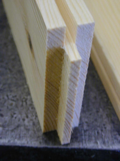
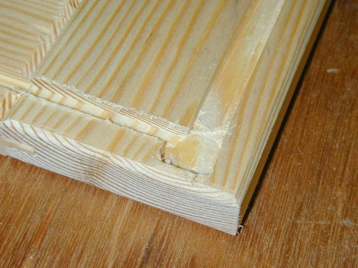
The tenon section was then cut using a similar technique but with the timber flat on the table to cut the shoulders. A couple of extra passes over the blade then removed the remaining waste (all these cuts were setup with scrap offcuts first to get a good fit):
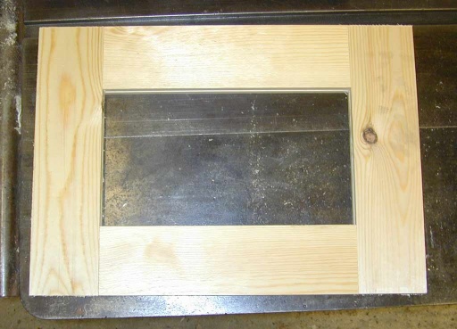
A test fit of the drawer frame came out like this:
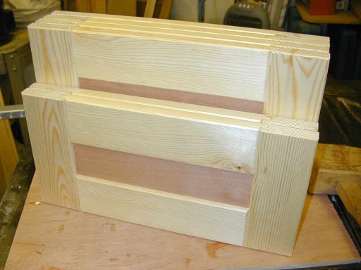
To add a little interest to the frame, a small 45 degree chamfer bit was used in a trim router to add an edge detail to all the edges. This was also done at the joint intersections so that it would leave a vee shaped groove in the finished frame where the stiles join the rails. Finally the ply insert panel was cut, and the drawer fronts glued up and assembled. A frame clamp was used to pull them all together, however once assembled the tenons held everything firm enough to not require further clamping. The completed fronts:
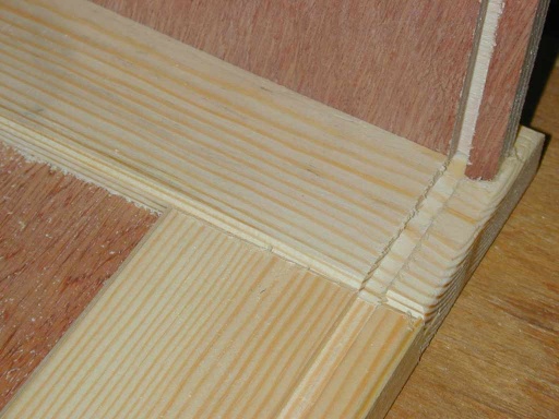
The backs of the drawer fronts were then routed to accept the sides and base. The base was to be in the thin ply, and the sides in the 12mm ply:
This was done with a hand held router, and a fence to provide a 1/2" offset from the sides and based of the drawer. First all the drawers were routed with a 6mm bit, and then the sides were re routed with the same bit at a bigger offset to enlarge the dado to take the wider ply sides.
The ply for the sides, back and base was also cut. The sides needed to be grooved to accept the base (done with two non-through cuts on the table saw - although the router would have done just as well), ans also the filing cabinet drawers also had a section notched out of the outside top edges, to leave 4mm wide "rails" that the suspension files could sit on.
The ply sides are deliberately shorter than the drawer front to allow clearance for labels on the tops of the suspension files.
The drawer back was cut from 18mm ply to the full width of the drawer, and a couple of cuts on the table saw were used to take a 1/2" square notch out the inside vertical edges of the drawer. This created a rebate that the edge of the drawer side could sit in. The height was slightly less than that of the sides to allow for the fact the back only reaches down as far as the top of the drawer base, which was to be inserted last.
The first bit of assembly was to glue the sides into the rebate in the drawer front:
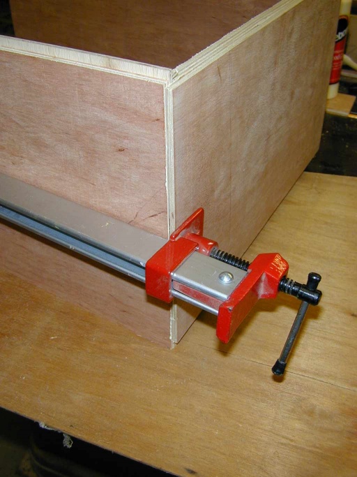
Then a couple of scraps of thin ply were set in the base groove to provide alignment of the back, and the back panel glued up and placed into position on the ends of the sides. This was then clamped tight along the length, and 30mm 18g brad nails shot into the corner joint from the back, pinning it tightly together:
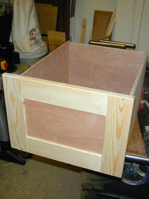
The clamp was then placed across the draw and that joint nailed when pulled up tight as well. The last job was to glue up the base rebates and slide the base into position. This was pinned to the bottom of the back panel, and any overhang trimmed off with a flush cutting router bit. Once completed the drawers looked like:
Doors
Since the the cupboard door design was essentially just a very large drawer front, these were completed at this stage as well, using the same techniques:
Base Unit
The base unit is a simple affair with a plinth, and then 5 boards to make a bottom, top, two sides, and a central divider. The plinth was simply a large H section cut from some scrap 1/2" MDF. This was designed to be a little less deep than the whole unit to allow a small kick space under the front of it.
The base was then cut from the thick ply, as was the central divider (since this was to have drawer runners screwed to both sides of it, the thicker stock meant there was less likely to be a problem with screws hitting each other!).
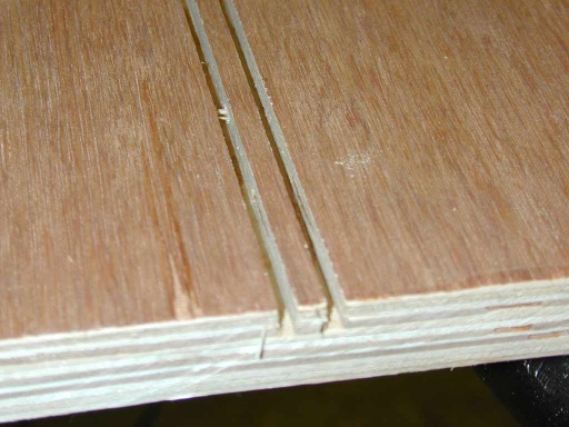
Dados were then cut in the base to house the vertical boards. Since these were somewhat under sized ply (the 1/2" ply was more like 11.7mm), these were cut as a pair of carefully laid out saw kerfs, and then the central section simply snapped out with the edge of a card scraper:
(being ply, the small central section de-laminates without too much protest!)
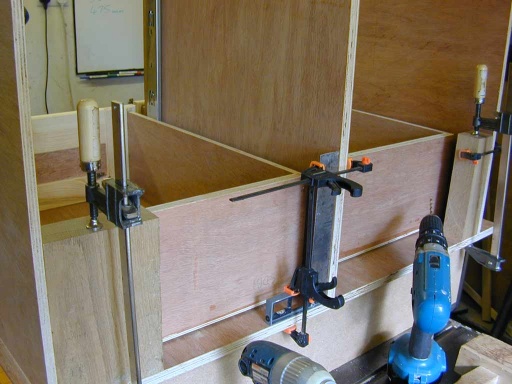
The base board was then screwed to the plinth, and the sides and central boards glued up and inserted. Two of the drawers and their runners were also put in place to make absolutely sure the spacing was going to be right! Some blocks of wood were also clamped into the corners while the glue set to make sure the whole construction at least started out square:
- with 20/20 hindsight here, it would have been better to include an additional sheet of ply for the top of the plinth (i.e. to sit under the base unit). Then rather than fix the plinth to the base, it could have been installed in the final position and then trimmed / wedged / shimmed until perfectly level. This would save any risk of pulling the base unit out of square when installing it, due to errors in the level of the plinth.
Finally, matching dados were cut into the underside of the worktop (3/4" MDF), and then that was glued up and dropped into place on the tops of the verticals. (the dados were cut to be a nice snug fit, so that it could be tapped home with a large hammer!)
(note the top has a wider overhang on the right hand side - this is to allow it to be fitted around the corner of the chimney breast at a later stage).
One of the last stages of the base unit construction was to make the face frame, and to cut lippings from some of the left over strips of PAR softwood. There were cut to size on the table saw, planed off by hand, and then glued and brad nailed to the edges through the face. (the pressure on the nailer was turned up a bit to make sure the nails were punched well under). These holes would be filled later. The same 45 degree chamfer bit was also used to detail the edges of the lippings and frame as had been used for the drawer and cupboard edges. The frame and lippings cover the edges of the ply, and also create the additional "width" required either side of the drawers to fill the left over space (and make sure the drawers open past the radiator on the adjacent wall!)
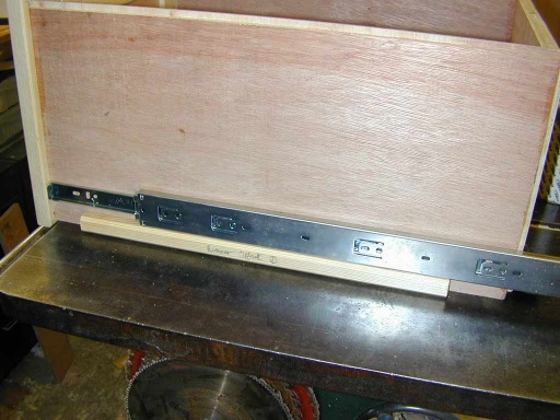
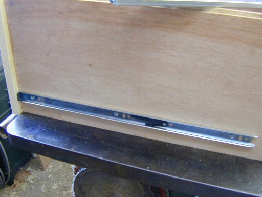
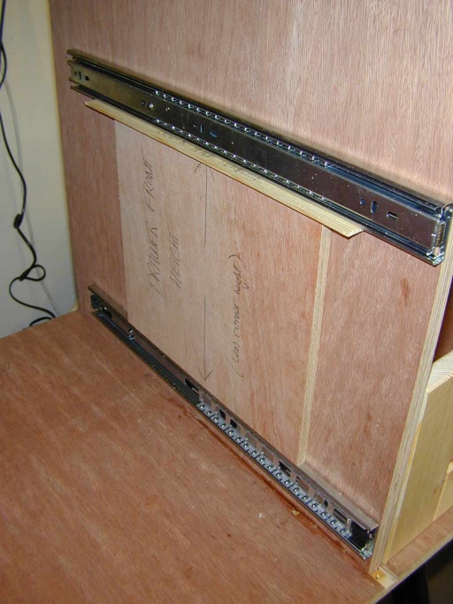
The final (and most tricky) job was fitting the drawer runners to the drawers and the carcass. This was done with a number of spacer blocks cut for the purpose, to ensure the same positions could be achieved each time. First the inner section was fixed to each drawer:
The drawer runner could be opened a little and the first screw fixed, then progressively slid more open and the others inserted. Until finally the catch could be flipped to release the inner runner altogether:
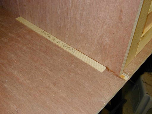
Next you need three templates to get the first runner in place in the cabinet, the first gives the offset from the base of the drawer front to the base of its sides (remember the face frame of the drawer front under hangs the bottom of the sides by a small amount (as you can see from the extra screw holes in the side in a later photo - I forgot this the first time round!)
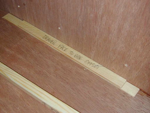
Next you need a spacer equal to the space that you want between each drawer. I used one of about 3mm here since the drawers could end up being quite heavy when fully loaded, and I wanted to make sure they stayed clear of each other!
Finally, the same template used for setting the height of the runner on the side of the drawer itself, was reused to allow for the distance from the base of the drawer side to the runner:
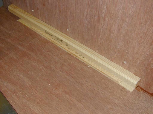
That gets the first four runners in place. Now you need one more template to space the next runner one drawers height higher, this is used with the drawer spacing template to push the next runner up by a drawer height plus a drawer gap height:
The same trick is used for the top runners as well since although they are shorter, they are still a "big drawer" higher.
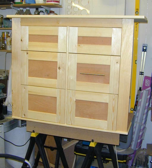
Apart from and extra strip of wood added later to add some more visual "weight" to the edge of the worktop, the addition of a lipping to the edged of the worktop, means that is the base unit basically done:
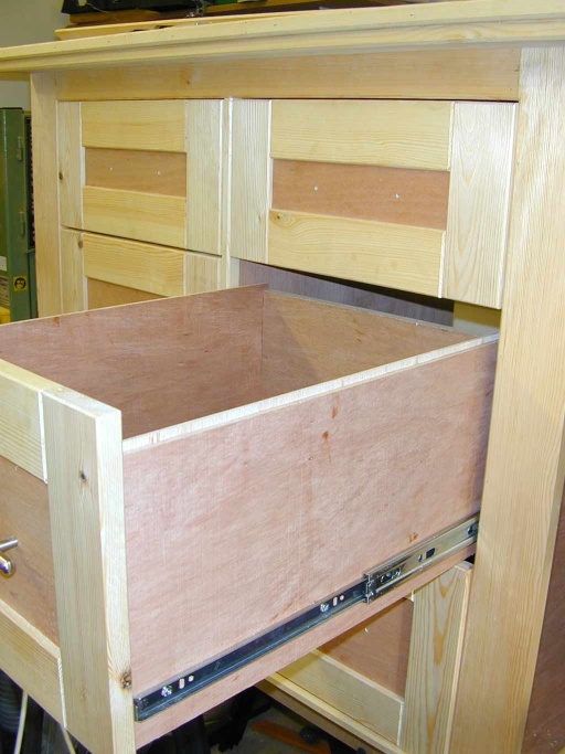
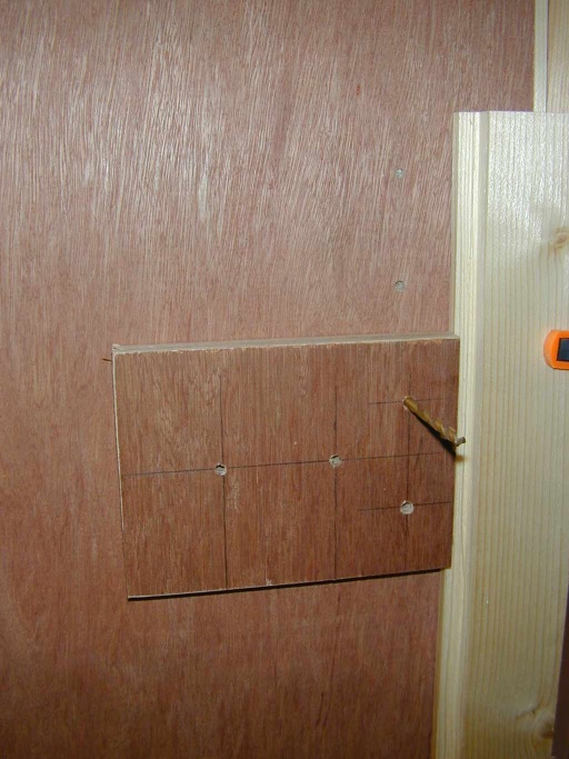
A template was made from a scrap of ply to drill the holes for the drawer handles. And one test fitted to make sure all works as expected:
You can see the three part runners allow access to pretty much all of the drawer's length.
Top Cupboard
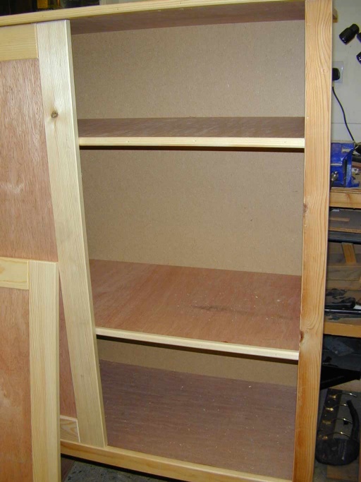
In comparison the the base unit, the top cupboard is pretty straight forward (and hence the place I made most of the silly mistakes!) The side are approx 1.5m tall, and are cut from 1/2" ply. They are rebated for the lower shelf (cut from the thicker ply). The top shelf is also cut from thick ply, but this is rebated to sit on the top of the sides and "fly over" each edge. Again the edges are set into rebates in the underside of the top. There are two floating shelves designed to sit on adjustable shelf support "thingies".
Since unlike with the base unit, one can see into the cupboard, it also has a fitted back cut from 6mm MDF in a couple of sections (the back also adds substantial rigidity to the whole unit). One does the enclosed section of the cupboard, and one the bottom open section. This is set into rebates cut into the back edges of the sides and top and bottom shelves. A softwood stringer is placed across the back at the bottom to carry the loose edge at the base of the unit.
Finally a face frame is made up from more softwood. The horizontal member under the cupboard doors is tenoned into the sides for added strength. Lippings are added to all the shelves, and the same chamfer cut on all the edges:
The left hand side of the face frame is left a little wide to allow it to be scribed to the wall. The right hand end is intended to sit flat against the front edge of the chimney breast.
The final job for the top cupboard was to drill the holes for the shelf supports. This is one of those jobs that is deceptively difficult to do well, since you need four sets of evenly spaced holes, that all line up perfectly with each other unless you want a wobbly shelf!
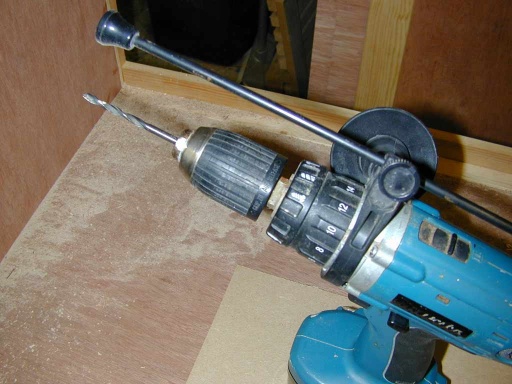
To do this I created a small template with two 5mm holes drilled through it, equally spaced about an inch in from top and bottom, and about 2" apart. I clamped a straight edge to the cabinet, and used a spacer block to position the template for the first hole. Using a 5mm lip & spur drill bit in the drill, fitted with the depth stop set to allow a maximum hole depth of about 5mm:
I drilled the first hole. Then placing a second spare 5mm drill bit into the first hole of the template (blunt end first), this was plugged into the hole just drilled - "pegging" the template in place for the next hole. The second hole in the template was then used to guide the drill for the next hole. After each hole was done, the template was moved down to index off the previous hole. (normally repeatedly indexing from your last measurement is a great way to compound any measurement error - however in this case we don't actually care about the absolute error over the sequence of holes, all we want is each to be the same distance from the last as the previous one!). The same trick repeated three more times, to leave four nice runs of perfectly spaced holes.
(with 20/20 hindsight, I could have drilled right through the sides and not fussed with limiting the depth in this case, since you will never see the outside of the top!)
Finishing
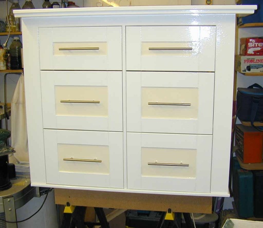
First job was to paint everything in primer. Then fill any blemishes and knots etc with a two part quick setting filler. Then it hand a sand, and an undercoat applied (with a small 4" roller on a long handle - did the lot in half an hour!). After that a final de-nib with some 400 grit wet'n'dry, and a coat of Johnstones brilliant white liquid gloss for most of it, and some Berger non drip magnolia gloss for the panels:
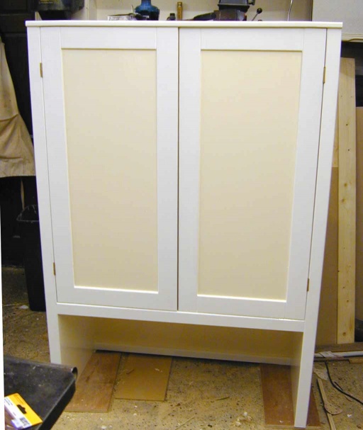
Same treatment for the top cupboard:
(The inside of the cupboard was just given two coats of acrylic gloss straight onto the bare wood with a long handled mini roller).
Installation
After the paint had had a couple of days to dry (and a suitable victim had been selected to help hump it all into position), the last job was to clear the corner of the office and fit the cabinet.
Once the corner was clear, I could measure the corner cutout required accurately, and jigsaw out the section of the top required to allow it to fit into the gap.
Since the base unit fills all of the width, it needs to go into its slot fairly squarely. Unfortunately this means the radiator was in the way. So we set it up on the same trestles it had been on in the workshop, and then slowly edged them into the gap with it on top - well clear of the rad and its pipes. Before finally pushing it against the wall, pulling the trestles out, and letting it slowly drop down into position! (taking all the drawers out also made it a tad lighter)
We then placed a couple of scraps of 1/2" MDF on the top to protect it while we fiddled with the top. This was slid mostly into position, and the left hand edge scribed to the wall. This was then cut in position with the jigsaw and tidied up with a block plane. The next problem was that we discovered the alcove narrowed slightly to the rear, requiring a small amount to be trimmed from both the sides at the back of the top of the cupboard (still no job is complete until you have had to reach for the Multimaster to dig you out of a hole!)
This allowed the top cabinet to be pushed home, and its floating shelves installed in the appropriate place. Once happy with the position, the MDF scraps could be removed.
The last job was to multimaster a couple of socket sized cutouts from the left side panel of the open section, to retrieve the loop of cable I had crimped into the ring circuit that fed the socket that was going to be obscured by the base unit, fit some dry lining boxes, and wire up the pair of double sockets.
The result
(excuse the slightly grotty photo - but it required a rather wide angle lens to get the shot, and the lighting was not that good!)
The last job is to paint up and fit the decore panel to the lower right side of the base unit, to return it neatly to the wall, and then to fit some matching skirting along the bottom under the plinth.
CD and DVD rack
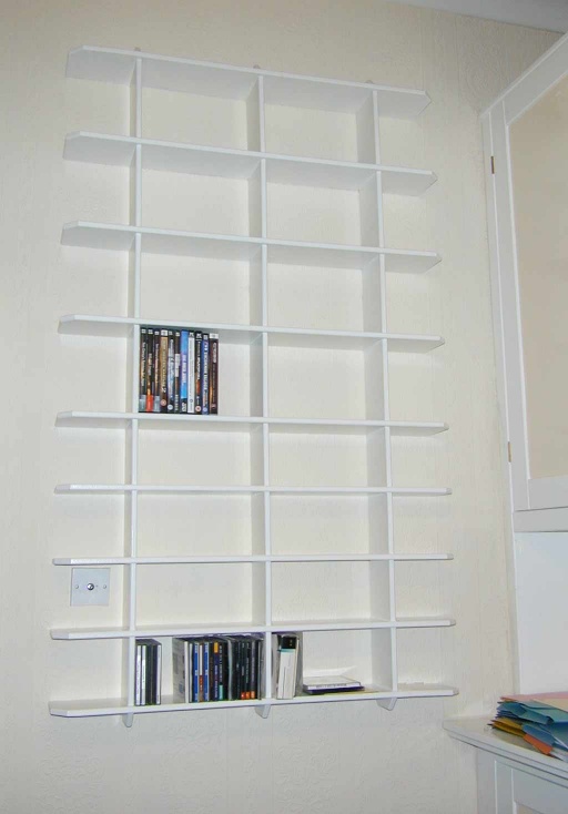
The final bit of furniture was the CD / DVD rack designed to take all the computer related media that has built up over the years and been accommodated in a number of boxes and racks etc. This was actually made before the cabinets themselves, but needed to wait until after they were installed to be usable (not only that, I was putting off the tedious process of painting it!)
So the finished result (after a coat of emulsion on the wall):
The entire rack was cut from a single sheet of 1/2" MDF. Using a half lap construction where the uprights meet the shelves. Its simply "hung" on the wall using three protruding screws that poke out of the wall and sit in holes drilled in the back of the uprights just below two shelves down.
