DIY eBike Conversion
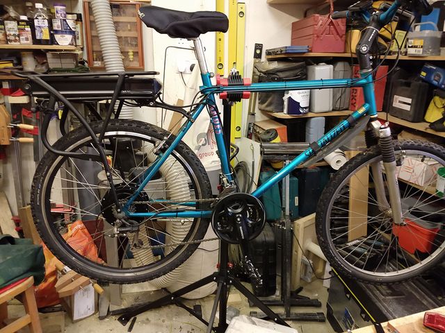
This is a recap of a project to convert my ageing mountain bike into a Pedal Electric Assist bike or "eBike". There are plenty of places that will sell you a whole new eBike, but conversion of an existing bike seems to be a less commonly explored option. However since my bike rode nicely and suited my needs well, it seemed like an interesting option. To keep the process relatively simple I started with a Shengyi DWG22C 48V 250W Rear Hub Kit with 48V 15AH Rack Battery conversion kit purchased from Woosh Bikes.
What is an eBike?
An eBike is bike fitted with an electric motor, a battery and, a control system. They typically work by detecting when you peddle, and then providing some additional "assistance" to reduce the effort required. The level of assistance is usually selectable from a number of levels. Some systems may also include a throttle facility to allow the system to power the bike even when not peddling.
Road legal eBikes on the UK have motors with a power limit of 250W, and must have a maximum assist speed of 15 mph (you can ride faster than that, but after 15mph is reached you are on your own, the motor will not assist further). If you exceed these limits then your bike will then be classed as a motor bike, and will be subject to the same requirements; i.e. will need to be insured, and the rider appropriately licensed.
Types of Motor
There are a number of ways that a motor can be added to a bike, but notably hub motors, and drive train motors. Hub motors, as their name suggests, are built into the hub of a special wheel. You can get appropriate wheels with motors to replace either the front or back wheel. Drive train motors tend to be mounted on the main frame of the bike, and nearer to the pedals. These provide their power input into the shaft driven by the pedals, so that the motive power is taken to the rear wheel via the sprocket and chain drive system along with the manual input from the rider.
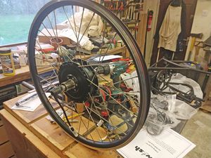
For this project we are going with a geared hub motor mounted in a new rear wheel. This will leave the existing 21 speed drive train largely untouched.
The conversion process
My Bike
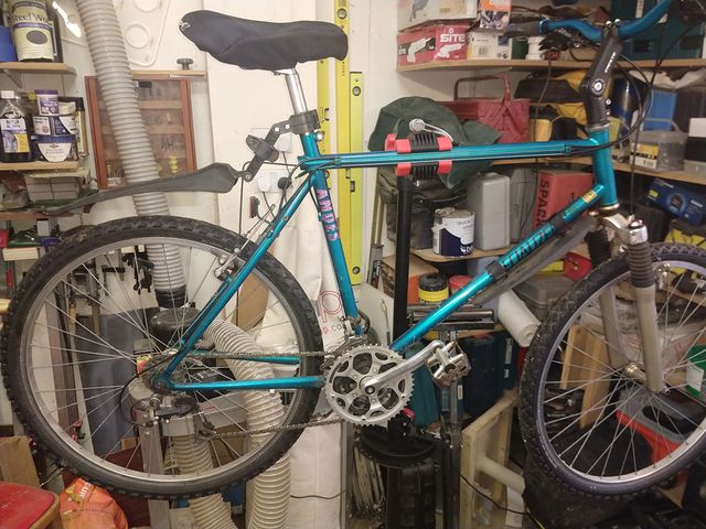
The bike I am converting is an aluminium frame 21 speed mountain bike made by Specialized. It dates from the 90's (probably) and was second hand when I bought it in the early 2000s. It's fairly light weight and sturdy. It has some upgraded front forks that were added before I got it. I have also swapped out the original handlebars and stem, for a taller adjustable stem, and handle bars with a bit of "lift" to them, to achieve a more comfortable upright riding position. (I used to find that with the saddle set quite high to cope with my long legs, the ride was a little too "prone" for my liking).
Getting started
To do a conversion like this you will need a few specialist bike tools for taking apart the pedals and crank set, removing the bottom bracket bearing, and for dismantling the rear derailleur cassette. A proper bike stand is also highly recommended unless you like working in awkward positions and have several pairs of hands!
Stage 1 - fitting the crank rotation sensor
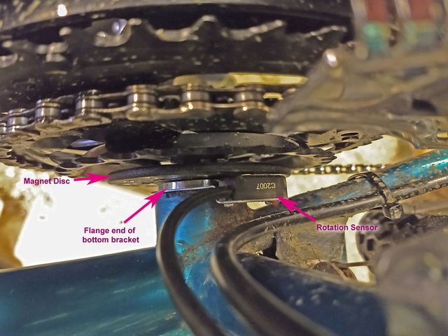
To be able to sense the rotation of the pedals, you need a crank rotation sensor. Most of these consist of a disc that one fits to the crank shaft, and a sensor module that is either mounted to the bottom bracket itself, or fixed to the seat tube on the frame. The disc typically contains a ring of small magnets, and the sensor a couple of hall effect detectors to sense the movement of the magnets as they pass the sensor. You can get sensor sets designed for fitting to either the left or the right hand sides of the crank. There are also some that fit to the inside of the chain wheel rather than onto the crank shaft itself. A few are available that fit to a spoke on the wheel (although these are far less desirable since you will then need full wheel rotations before the sensor can "see" the movement).
I opted for a sensor designed to mount behind the flange on the bottom bracket, and a magnet disk that mounts to the right hand side of the crank shaft behind the chain wheel.
To fit this, you need to:
- Remove the crank and chain wheels on the right hand side
- Remove the bottom bracket
- Fit the sensor over the bracket and refit to the frame
- Fit the magnet disc on the crank shaft
- Refit the chain wheels and crank.
Now here is where I met the first few interesting challenges. Since my bike dates from the 90's, it uses a square drive tapered crank bottom bearing. On this setup the crank set, is retained onto the shaft by a single screw that draws the crank onto the square drive shaft. Since the crankshaft is tapered, there is a strong interference fit between the crank and the shaft. Removing the retaining screw is easy, however this does not actually free the crank from the shaft. To do this you will need a special crank puller tool.
The puller tool has a threaded section that screws into a rebate on the crank, and then a threaded push rod that then passes through the screw hole in the crank, and pushes against the end of the shaft. As you tighten the push rod it should pull the crank off the tapered shaft. At least that was the theory. It looks like my crank has been taken off before and the outer section of threads were not looking too healthy. Needless to say rather than freeing the crank, all I succeeded in doing was to strip the remaining threads on the crank!
So while I contemplated fashioning a bearing puller that could do the trick without relying on the threaded socket on the crank, I noticed another anomaly on my bike. Normally the bottom bracket crank shaft arrangement has a "fixed" end and a separate "shell" end. The fixed end normally screws into the frame from the crank wheel side, and the free shell bit is then screwed in from the other side. On my bike the bottom bracket was actually screwed in from the other side. This meant that if one undid that side, it pulled the chain wheel toward the frame until it hit the other side of the bracket - in effect pulling the square drive shaft away from the crank.
Using this as a bearing puller alone would be risky, since as you withdraw it form the frame there is ever less thread engaged, and I really don't want to strip the threads on the frame! However I went for the combination of treating the shaft with some penetrating oil, then adding PTFE tape to the proper crank removal tool, and refitting that and adding as much pull as one could without causing that to pull out again. Then undid the bottom bracket and applied some pull from that. Lastly I warmed the top of the crank with a blowtorch. Finally a couple of taps with a soft faced hammer popped the crank off nicely.
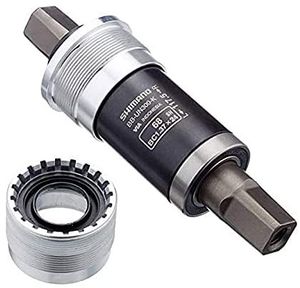
So while refitting the existing crank set would be easy, I did not fancy the same hassle again in the future and ordered a new Shimano Altus FC-M311 Crank crank set with the same wheel tooth counts. Closer inspection of the bottom bracket also showed that its bearing seals were knackered, and the free shell end was only a plastic part rather than ali. So I also ordered a new Shimano BB-UN300 bottom bracket (British thread, 68-122.5 mm). This one is also threaded so that it could fit from the more traditional side. I opted for one that had a 5mm longer shaft to allow more space for the magnet ring behind the chain wheels.
So with those delivered, I could finally refit the bottom bracket, with the hall effect sensor mounted behind it, then the magnet ring, and finally the new crank set. Alas the new cranks had some protruding lugs on the inside of the small chain wheel that were not on the previous set, and these were going to get in the way of the magnet ring! So a little fettling with an angle grinder and die grinder got shot of those!
Stage 2 - fitting the new wheel
The next job was to fit the new wheel containing the hub motor. This sounded like it ought to be an easier job! So I disconnected the brake calliper, undid the quick release leaver and dropped out the wheel. The first job was to then take the tyre and inner tube off the old wheel and refit it to the new one. (the new wheel has a much deeper central "well" that made tyre fitting much easier).
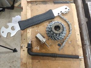
Next job was to remove the rear derailleur cassette from the old wheel. For this you need a special tool that can engage with the splines on the inside of the smallest sprocket. This lets you remove the retaining cap, and the whole set of gears sides off the shaft. You also need a sprocket chain tool that lets you get a grip of the sprockets safely and stop them from spinning on the free-wheel ratchet while you undo the gear set.
In this case the cassette consisted of 6 gears in one block, and then a separate single small cog with a spacer to go between them, and the final splined cap to screw into the end of the wheel gear shaft that retains them.
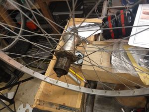
Refitting ought to be easy, however I met two problems here. The first is that the new wheel has a shaft with enough depth to take an 8 gear sprocket rear cassette, and mine was a 7 gear one. Hence there was too much slack to tighten up fully and stop it slopping from side to side on the shaft. The second issue was that my original sprocket tool, has a central post that passes into the axle hole, and helps locate and centralise it in the gear set. The new motor hub does not have an axle hole - the power feed wires emerge from it in the space that would otherwise be used by the "skewer" style axle, so there is no space for the centre post! So since I needed to order a set of spacer rings to properly fit the gear cassette, I also ordered a new tool that did not have the central post.
So with a bit of experimentation, I found that a 1.5mm spacer ring adjacent to the large cog, then the block of 6, then a 1mm spacer ring, the final small cog, and lastly the retaining cap. It took a bit or trial an error to get a working setup with the cogs in the right places and a snug fit. (not helped when I forgot that there was a spacer ring originally installed between the small cog and the cassette, and without this the chain was catching on the adjacent cog when running on the smallest cog).
I was about this time I went to refit the pedals and realised that the bearings on one of those was a bit rough and lumpy. So I treated it to a new set of them as well.
Stage 3 - New user controls
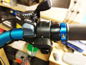
For safety, the eBike controls should have a sensor input from the brake leavers to indicate when the brakes are applied. This is used to cut the motor power so you can't ever get a situation where the motor continues to run when the brakes are applied. This can be done with brake leavers that include a sensor, or with separate add on sensors. I had planned to go for the latter but these were out of stock, so I had to order the new leavers instead. My existing leavers were combined brake and gear shift leavers. While the right hand one shifted nicely, I was never that happy with the left hand one, since it tended to slip position (not helped by a crack in the gear select mechanism). So I ordered a set of Shimano Tourney SL-TX30 Thumb Gear Shifters in the "3X7" configuration. These are rather nice since they have a button operated "up" shift on the right hand side that quickly indexes the next higher gear with a single button push.
With all that it was then a case of arranging everything on the handlebar and getting all the angles and spacing to feel right when riding.
Stage 4 - Gear linkages
Now the new shifters were fitted I could turn my attention to the gears and getting the new control cables hooked up. The rear was easy, and took very little adjustment (a tweak to the limit screws to match the position of the end sprockets) to get that working nicely. It's quite satisfying to just push the button and it step accurately through each gear.
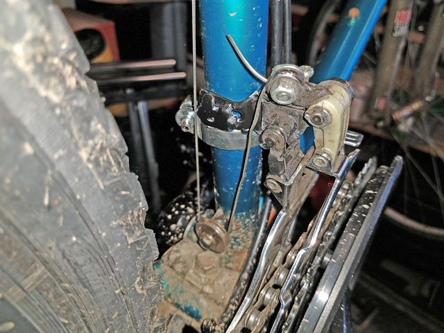
The front derailleur was a bit more of a challenge however since I could not get it to shift the chain to the large cog. It was always a bit tricky to select in the past, but was made more difficult by the slightly longer bottom bracket shaft I had fitted, moving the whole chain wheel set further away from the frame by an extra couple of mm. Ideally it would be nice if one could adjust the reach of the cage on the derailleur. However this could not be done on mine. So I ordered a slightly different design Shimano Front Mech TY510 66-69 T/S multi 48T, which was designed for bikes with a larger diameter seat tube (but included spacers that would allow it to fit on smaller ones). My logic here being that since I had the slimmer 28mm diameter seat tube, I could fiddle with the spacers on the bracket, and if needs be, shift the position over slightly that way. This was fine in theory, however what I neglected to spot in my haste ordering (it was getting close to Christmas - and I only wanted stuff I could get before then) was that this design could only cope with a 20 tooth maximum difference between smallest and largest chain wheels. Since I had a 24 tooth difference, that meant that there was no way to position it where it would not end up with the chain rubbing on at least one end of its movement.
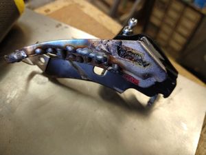
Enter "frankenderailleur". So the final solution was a bit brutal, but worked a charm. I set about the new mechanism with an angle grinder and chopped off its cage and mechanism, leaving nothing but just the seat tube bracket and stub of metal. Then got my original mechanism, chopped off the hinged side of the seat tube clamp, and flattened out the fixed side in the vice, and chopped off the section at the end where the retaining bolt used to screw into. This basically just left a straight metal tab that stuck out from the side of the mechanism. Next I fitted the new clamp to the seat tube, and offered up the old mechanism, and slowly chopped and ground the parts until they met neatly, with the mechanism in the right place, at the right angle, and with the right reach. I clamped the bits together with some pointed nose vice grip pliers, and removed them from the frame. Lastly I setup the welder, and joined them permanently. (Since I now had a spare derailleur cage to hand, I used that for some test welds to get a suitable voltage and wire feed rate dialled in, since I was only going to get once chance on the real thing.
That worked a treat, now the limits could be set on the front mechanism, and it could reach all the cogs and cope with the diameter difference between smallest and largest chain wheels.
The one remaining tweak needed was to the puller cable pinion wheel that the control cable is looped round to allow the cable to pull down on the mechanism. This was positioned a bit too close to the down tube for frankenderailleur. So a new longer M5 bolt was found, and my collection of spacers left over from fitting kits that came with various TV and monitor brackets, was raided for an ali spacer close to the right length. A quick lick with the angle grinder got that to the required length.
Stage 5 - Fitting the battery rack
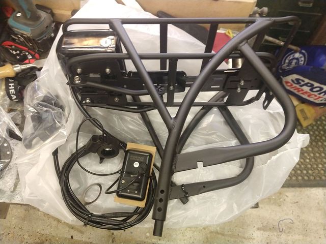
There are a number of battery styles that one can order. I was initially going to go for the 13Ah battery mounted on the down tube, but in the end decided to go for a rear pannier mounted one since the bike did not have a pannier, and it might actually be useful to have some carrying capacity, and also it allowed for the slightly larger capacity 15Ah battery to be used. (this is estimated to allow around 60 miles of range - although that probably does not allow for the bulk of the current rider!)
The frame already had threaded holes and bosses in the places required for the pannier. The ones on the rear hub bracket of the frame looked like they had never been used and were still full of paint. So I had to stick a M5 tap through them first. Also I needed to find some longer bolts for these (more from the flat screen TV fitting kit!). A bit of careful bending of the top brackets was required to get them to meet the pre tapped holes in the frame at the right angle to get the screws in.
Stage 6 - Wiring it up
The last bit was to get it all wired up. This is fairly "plug and play" (literally - all the cables are pre-terminated in plugs and sockets). However some thought needs to be applied to route these around neatly and zip tie them to the frame in the appropriate places. One end of the main control wire to the motor ended up under the pannier, and since I had removed the original mud guard, was likely to cop the full force of any spray coming off the rear wheel, so I cocooned that connection in self amalgamating tape.
(I have now extended the bracket for the mudguard and refitted it between the wheel and the pannier)
Trying it out
Once it was at a ridable stage (this was before finally fixing the front derailleur problem), I decided it was time to try it. Alas it was very damp, soggy, and rather too cold for this fair weather cyclist's liking, So me and the bike got covered in spray and mud (hence the state of it in some of the photos!), but you know, boys and their toys!
All in all it worked very well on its initial spin round the local country lanes. The pedal sensor notices that you have started pedalling within less than half a turn of the crank, and brings the power in. On the minimum assistance level this translates into a drop in resistance pedalling, and it will keep assisting gently up to around 8 mph. As you switch up to higher assistance levels the amount of extra oomph becomes more noticeable and the speed at which it stop assisting gets higher (each level adds ~2mph). As you reach the limit speed it backs off the assistance progressively. So on the top level it will assist firmly until around 15.5 mph, and then start reducing as you go quicker. Once a bit beyond 16 you will go no assistance at all. The progressive nature of the tail off is nice since it means you can set a comfortable speed, and ride at it or just over, with the motor only contributing when needed.
The power allows for more rapid acceleration and ascent of even moderately steep hills much less peddling effort if desired. You can pull away in a higher gear. You can make progress into stiff head winds without having to slow your progress. If you prefer to ride in bursts of effort, then the thumb throttle comes into its own, since you can have the bike take over for a spell while you have a rest! The thumb throttle also has the advantage of being infinitely variable unlike the preset levels of assist. So when matching the speed of another cyclist travelling at a speed that does not match one of the preset levels, you can use the throttle instead. It is also good for when riding mostly unassisted, to give a quick squirt of power on the occasions you want it.
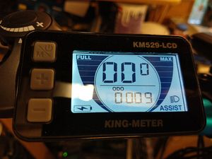
There is also a "walk assist" mode that allows a slow (~4 mph) drive to be delivered to the bike while you hold a button on the control panel. This is designed to make it easier if you need to push it up a hill or similar.
The second trip out was just a couple of miles to test out the fixed front gear selection issue. That worked nicely. The 15 mph speed limit of the system means that the assistance is best matched to the first two front sprockets, since the big one is better suited to riding faster. This is probably the ideal since it will tend to be at these speeds one is climbing hills or pressing into strong head winds. One can ride with the assistance turned off completely as well should you fancy (or if you run out of battery). The geared motor that I selected adds no drag of its own - you can still free-wheel.
Brakes
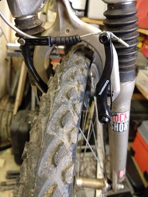
One not so good thing was the braking. Previously the cantilever brakes had been just about adequate but not particularly good. The new sensored brake leavers were probably geared with the anticipation they would be operating V Brakes rather than cantilever ones, and V Brakes need a more pull travel, which means the leavers have less mechanical advantage than the original set. (The additional weight on the bike (and me!) probably does not help either).
So the final upgrade was to swap out the cantilever callipers for V Brake callipers. Although there was less available choice than in the past (discs and a modern take on side pull callipers seem more in fashion), it was easy enough to find a set that would be a drop on replacement for the original cantilever ones. Annoyingly it also meant swapping out the rear break cable inner for a longer one as well. However the change worked a treat, and finally the bike feels like it would actually stop in a hurry if required!
Conclusions
Since we live in a location where going any distance usually involves a hill of one description or another this should give a bit more encouragement to ride more and further afield since there is no longer the mental block of "too steep that way!" Also since my wife also has an eBike, I ought to be able to keep up with her!
It is worth noting that the extra kit does add extra weight to the bike - probably getting on for 8kg or so. Hopefully with a bit more riding I should be able to reclaim some of that weight gain off the waistline!
Since I used the rack battery, most of this is toward the back of the bike, making the front feel a little lighter (at least while manhandling it about rather than riding). For road riding the change in balance is not going to matter, however if I were more into off road riding, the down tube battery would probably be a better choice since this would shift some of the weight gain toward the front of the bike.
Total cost of doing the conversion was approx £640 for the kit, and then I spent around another £125 on replacement parts along the way. Most of these were actually replacing bits that I had not realised where quite as worn out as they turned out to be, but that did include a new set of rechargeable LED lights.
With hindsight it might have been better to have opted for a left hand side pedal sensor, since that may have saved altering the front gear selector or chopping the lugs off the back of the new chain set and cranks.
1000 miles on
I thought an update might be in order after 8 months of riding, and the first thousand miles have been surpassed. The fact that is this is a considerably larger distance than the combined distance I have ridden in the last couple of decades ought to tell you something! Having the power assist available takes the fear out of a ride, you no longer worry about routes that include hills, or trying a ride that might be a bit too far, since if you do find yourself flagging toward the end, you know the bike can help! You feel safer at junctions and in traffic since you can get out of the way more quickly.
Battery performance has been surprisingly good. Typically I charge it no more than twice a week, and ride nearly every day. Minimum daily ride distance is typically around 5 miles, quite often 10 to 14 miles, and then often a longer 20 to 25 mile trek on a weekend. 40 miles of range is easily achievable. (the biggest influence is probably the wind). Much of the ride I can keep the pace up beyond the level of assistance, and so drain on the power then is minimal or zero.
I have discovered lots of interesting countryside that has been on my doorstep for years but previously unexplored. Also quite pleasing, is that I have reclaimed all of the weight I added to the bike (and more) by trimming it off me :-)
Changes
Since the work described here, I have kept the bike mostly unchanged. However I have tweaked a couple of bits. As my fitness improved I found myself using the higher range of gears more, and also longed for a slightly taller top gear for downhill sections. So I swapped out the rear cassette for one with a smaller 12 tooth top gear. I now find myself riding predominantly on the large cog of the front gear, and gears 3 to 7 on the back. I also changed saddle for one with some springing (no suspension on the back of the bike, plus a fair amount of weight made for quite a "robust" reaction to pot holes!). I added an extension between the steering tube and the handlebar riser, to add about 3" and get a slightly more upright position (and a little more forward tilt on the handlebar bracket - which makes the steering a bit less twitchy). While this will never win any awards for aerodynamic efficiency (lets face it, at my 6'3" size the mostly upright posture gives me the aerodynamic performance of a wardrobe!) it is a more relaxed ride, that saves bending the neck so much to see where you are going (and means I am looking through my glasses and not over them!). It also also quite a "powerful" riding position since you are close to standing on the pedals without actually needing to stand). I added a small bag to the top tube to keep a small selection of tools, and spare inner tube etc it.
