Difference between revisions of "2 Way Switching"
(Added new diagram and some more description) |
|||
| (29 intermediate revisions by 3 users not shown) | |||
| Line 1: | Line 1: | ||
| − | ''' | + | '''Two way switching''' means having two or more switches in different locations to control one lamp. They are wired so that operation of either switch will control the light(s). |
| + | |||
| + | ==Two Way Switches== | ||
| + | |||
| + | A Two Way light switch is a simple single pole "changeover" switch with three terminals. These are typically labelled COM, L1, and L2 (Some may label the L1 and L2 positions as "1 Way" and "2 Way"). | ||
| + | |||
| + | In one switch position the COM terminal is connected to L1. In the other switch position it changes over so that COM is connected to L2. The design is a "break before make" type, such that the connection to the first terminal is disconnected before the connection to the new one is made. | ||
| + | |||
| + | [[image:TwoWaySwitchNamingConvention.png|thumb|left|First position]] | ||
| + | [[image:TwoWaySwitchNamingConvention2.png|thumb|left|Second position]] | ||
| + | |||
| + | <gallery> | ||
| + | file:2WaySwitchFront.jpg|The faceplate of a traditional UK style two way single light switch | ||
| + | file:2WaySwitchObverse.jpg|The terminals of the single light switch | ||
| + | file:2GangTwoWaySwitchFront.jpg|The face of a dual gang two way switch | ||
| + | file:2GangTwoWaySwitchObverse.jpg|The terminals on a dual gang two way switch | ||
| + | </gallery> | ||
| + | |||
| + | <br clear="all"> | ||
| + | |||
| + | ''Click images for enlargements'' | ||
| + | |||
| + | NOTE many single way switches will have a space for the L2 terminal, even though it is not fitted since the same plastic casing is usually used for both types. Some manufacturers (especially Hager) put an additional, insulated terminal in the switch, which can be used for looping through the Neutral. | ||
==Standard two way switching circuit== | ==Standard two way switching circuit== | ||
| − | To achieve | + | To achieve two way control the usual single switch is replaced with one of the following circuits: |
| + | |||
| + | [[image:TwoWaySwitching.gif|640px]] | ||
| + | |||
| + | A typical application is that of being able to switch the hall and landing lights on and off from both upstairs and downstairs. An implementation that allows both lights to be controlled from both locations could look like this: | ||
| + | |||
| + | [[Image:HalLandingSwitchingSml.gif|600px]] | ||
| − | + | ''(in the above example the landing light would be switched off, and the hall light would be on)'' | |
| − | |||
| − | |||
| − | |||
| − | |||
| − | |||
| − | |||
| + | Two way switches usually have terminals marked COM, L1 and L2. In the above diagram, the black core of the [[Cables#3.26E|3&E]] has been connected to the COM terminal, and the Brown to L1 and the Grey to L2. | ||
| − | + | ===Alternative method of Two Way Switching=== | |
| − | [[ | + | |
| + | This method is also sometimes seen, although its use is deprecated since live and neutral are connected at two different locations. One potential problem here is where the two switches are in locations covered by different circuits, you may end up with a live feed on one circuit connected to a neutral on a different circuit. This is not only dangerous, but often incompatible with [[RCD]] protected circuits. | ||
| + | |||
| + | [[image:TwoWaySwitchingDepricated.png|640px]] | ||
| − | + | Another failing of this layout is that it may generate additional electrical interference and "noise" since the current flow in the link cable between switches is unidirectional (most circuit cables have currents flowing in opposing directions in their separate wires). This can cause interference with inductive loop hearing aid systems for example. | |
| + | ==Three Way (or more!) Switching== | ||
| + | The addition of an "intermediate" cross over switch allows a two way switched lamp to be controlled from a third position. In fact any number of intermediate switches can be added, to add as many extra switching positions as required. | ||
| − | + | [[image:MultiWaySwitchingNormal.gif|640px]] | |
| − | + | An application of above using multiple switching positions to switch multiple lamps: | |
| − | |||
| − | |||
| − | |||
| − | |||
| − | |||
| − | |||
| + | [[image:MultiPointMultiLampSwitch.gif|677px]] | ||
| − | + | *The switches at each end are 1 pole 2 way switches | |
| + | *Any number of intermediate crossover switches may be added to give three or more switching positions. | ||
| − | |||
| − | |||
| − | |||
| − | |||
| − | |||
| − | |||
| − | |||
| + | ===Alternative method of Three Way Switching=== | ||
| − | + | This is an alternative deprecated form (see above for the reasons) of the multi way switch wiring: | |
| − | + | [[image:MultiWaySwitchingDepricated.png|640px]] | |
| − | |||
| − | |||
| − | |||
| − | |||
| − | |||
| − | |||
| − | * | + | *The switches at each end are 1 pole 2 way switches |
| − | + | *Any number of intermediate crossover switches may be added to give three or more switching positions. | |
| − | * Any number of crossover switches may be added to give | ||
| − | |||
| − | |||
==Notes== | ==Notes== | ||
| − | The first example given in each case is the preferred connection method, as it ensures the light is powered from the expected circuit (i.e. that feeding other lights on the same storey). It is also less likely to cause interference problems with electronic systems (the example given in the electrical regulations is inductive hearing loop systems but similar considerations apply to computer networks and other wired systems). '''Caution:''' Two way light switches in this switching arrangement will carry live wires from two independent circuits. | + | The first example given in each case is the preferred connection method, as it ensures the light is powered from the expected circuit (i.e. that feeding other lights on the same storey). It is also less likely to cause interference problems with electronic systems (the example given in the electrical regulations is inductive hearing loop systems but similar considerations apply to computer networks and other wired systems). |
| + | |||
| + | '''Caution:''' Two way light switches in this switching arrangement will carry live wires from two independent circuits. | ||
| − | The alternative circuits appear to require one less wire but in reality | + | The alternative circuits appear to require one less wire but in reality it is usually necessary to return the COM connection at the second switch position to the first switch or the rose or light fitting which typically needs a wire. They are included here as they are often encountered in older wiring. |
| + | |||
| + | '''Caution:''' Something to watch out for on circuits wired in this way, is lamps being powered from unexpected circuits (e.g. upstairs lamp powered from the downstairs circuit and vice versa), also the not uncommon practice of "borrowing" a neutral connection from a circuit other than the one providing the line connection. Needless to say this practice will cause [[RCD#Nuisance_trips|unexpected trips]] when a modern consumer unit incorporating multiple RCDs or RCBOs is installed. | ||
| + | |||
| + | Sometimes two way switched circuits are more likely to give rise to [[CFL#Occasional_flashing|occasional flashing]] problems when used with low power CFL or LED lamps. | ||
==Carter system== | ==Carter system== | ||
| − | Another | + | Another two way switching method exists and is occasionally encountered. Its called the Carter system (other names are also used). |
| − | + | Both the standard and alternative variations can be configured as a Carter system. Power is fed to the circuit in the same way, however the lamp is connected between the COM terminals of the pair of two way switches. Thus, depending on the switch settings the lamp can see either 2 neutrals, 2 lines, or one of each. | |
| − | This approach | + | This approach will with some switch settings leave both terminals of the lamp holder "live" even when the lamp is not lit, creating a shock risk for someone changing a bulb. It also feeds line and neutral to the poles of a switch, and switches do mechanically fail, creating the risk of a short. For these reasons this method has long been non-compliant, and should not be used. |
| − | == | + | ==Switching with multiple PIRs== |
| − | Another common requirement is to | + | Another common requirement is to allow one or more lamps to be switched by multiple PIR sensors, say for example automatically turning a a driveway lamp on when approached from both ends of the drive. This can be achieved like this: |
| − | [[image:MultiPIRandLampCircuit.gif| | + | [[image:MultiPIRandLampCircuit.gif|400px]] |
| − | Note the light switch in the above diagram can force the lights "on", but will leave them in automatic mode when in its "off" position. | + | Note the optional light switch in the above diagram can force the lights "on", but will leave them in automatic mode when in its "off" position. A second switch could be included at the start of the live feed to allow for a "completely off" setting. |
| + | |||
| + | When selecting PIRs for this application, make sure the switching capacity is large enough to support the load of all the lamps added together. | ||
==See Also== | ==See Also== | ||
| − | |||
| − | |||
| − | |||
| − | [[Special:Categories|Wiki Subject Categories]] | + | *[[House Wiring for Beginners]] |
| + | *[https://groups.google.com/group/uk.d-i-y/browse_frm/thread/f1b92cc95983c14b?hl=en# Doing it electronically] | ||
| + | *[[Wiring colour codes]] | ||
| + | *[[Special:Allpages|Wiki Contents]] | ||
| + | *[[Special:Categories|Wiki Subject Categories]] | ||
=Keywords= | =Keywords= | ||
Revision as of 10:14, 8 April 2021
Two way switching means having two or more switches in different locations to control one lamp. They are wired so that operation of either switch will control the light(s).
Two Way Switches
A Two Way light switch is a simple single pole "changeover" switch with three terminals. These are typically labelled COM, L1, and L2 (Some may label the L1 and L2 positions as "1 Way" and "2 Way").
In one switch position the COM terminal is connected to L1. In the other switch position it changes over so that COM is connected to L2. The design is a "break before make" type, such that the connection to the first terminal is disconnected before the connection to the new one is made.


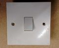
The faceplate of a traditional UK style two way single light switch
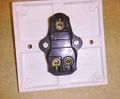
The terminals of the single light switch
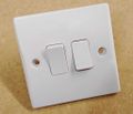
The face of a dual gang two way switch
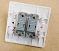
The terminals on a dual gang two way switch


Click images for enlargements
NOTE many single way switches will have a space for the L2 terminal, even though it is not fitted since the same plastic casing is usually used for both types. Some manufacturers (especially Hager) put an additional, insulated terminal in the switch, which can be used for looping through the Neutral.
Standard two way switching circuit
To achieve two way control the usual single switch is replaced with one of the following circuits:

A typical application is that of being able to switch the hall and landing lights on and off from both upstairs and downstairs. An implementation that allows both lights to be controlled from both locations could look like this:

(in the above example the landing light would be switched off, and the hall light would be on)
Two way switches usually have terminals marked COM, L1 and L2. In the above diagram, the black core of the 3&E has been connected to the COM terminal, and the Brown to L1 and the Grey to L2.
Alternative method of Two Way Switching
This method is also sometimes seen, although its use is deprecated since live and neutral are connected at two different locations. One potential problem here is where the two switches are in locations covered by different circuits, you may end up with a live feed on one circuit connected to a neutral on a different circuit. This is not only dangerous, but often incompatible with RCD protected circuits.

Another failing of this layout is that it may generate additional electrical interference and "noise" since the current flow in the link cable between switches is unidirectional (most circuit cables have currents flowing in opposing directions in their separate wires). This can cause interference with inductive loop hearing aid systems for example.
Three Way (or more!) Switching
The addition of an "intermediate" cross over switch allows a two way switched lamp to be controlled from a third position. In fact any number of intermediate switches can be added, to add as many extra switching positions as required.

An application of above using multiple switching positions to switch multiple lamps:

- The switches at each end are 1 pole 2 way switches
- Any number of intermediate crossover switches may be added to give three or more switching positions.
Alternative method of Three Way Switching
This is an alternative deprecated form (see above for the reasons) of the multi way switch wiring:

- The switches at each end are 1 pole 2 way switches
- Any number of intermediate crossover switches may be added to give three or more switching positions.
Notes
The first example given in each case is the preferred connection method, as it ensures the light is powered from the expected circuit (i.e. that feeding other lights on the same storey). It is also less likely to cause interference problems with electronic systems (the example given in the electrical regulations is inductive hearing loop systems but similar considerations apply to computer networks and other wired systems).
Caution: Two way light switches in this switching arrangement will carry live wires from two independent circuits.
The alternative circuits appear to require one less wire but in reality it is usually necessary to return the COM connection at the second switch position to the first switch or the rose or light fitting which typically needs a wire. They are included here as they are often encountered in older wiring.
Caution: Something to watch out for on circuits wired in this way, is lamps being powered from unexpected circuits (e.g. upstairs lamp powered from the downstairs circuit and vice versa), also the not uncommon practice of "borrowing" a neutral connection from a circuit other than the one providing the line connection. Needless to say this practice will cause unexpected trips when a modern consumer unit incorporating multiple RCDs or RCBOs is installed.
Sometimes two way switched circuits are more likely to give rise to occasional flashing problems when used with low power CFL or LED lamps.
Carter system
Another two way switching method exists and is occasionally encountered. Its called the Carter system (other names are also used).
Both the standard and alternative variations can be configured as a Carter system. Power is fed to the circuit in the same way, however the lamp is connected between the COM terminals of the pair of two way switches. Thus, depending on the switch settings the lamp can see either 2 neutrals, 2 lines, or one of each.
This approach will with some switch settings leave both terminals of the lamp holder "live" even when the lamp is not lit, creating a shock risk for someone changing a bulb. It also feeds line and neutral to the poles of a switch, and switches do mechanically fail, creating the risk of a short. For these reasons this method has long been non-compliant, and should not be used.
Switching with multiple PIRs
Another common requirement is to allow one or more lamps to be switched by multiple PIR sensors, say for example automatically turning a a driveway lamp on when approached from both ends of the drive. This can be achieved like this:

Note the optional light switch in the above diagram can force the lights "on", but will leave them in automatic mode when in its "off" position. A second switch could be included at the start of the live feed to allow for a "completely off" setting.
When selecting PIRs for this application, make sure the switching capacity is large enough to support the load of all the lamps added together.
See Also
- House Wiring for Beginners
- Doing it electronically
- Wiring colour codes
- Wiki Contents
- Wiki Subject Categories
Keywords
Two way, two way switching, two way switch, intermediate switch, multiple light switches, switching a light from two locations, twin switches, two way wiring, hearing aid compatibility, remote switching