Cabinet clock
Introduction
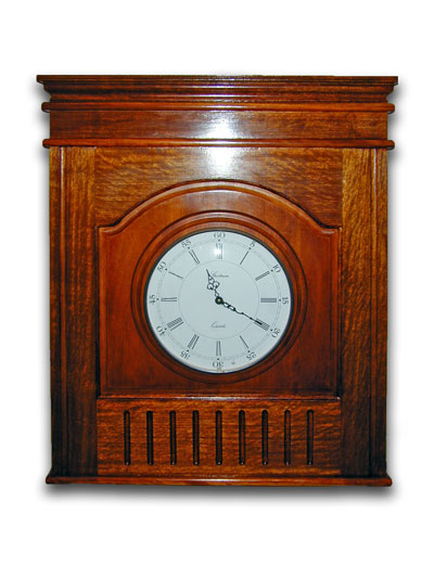
This article describes the construction of an ornate cabinet with a mounted clock (plus a twist!). This is an heirloom project, with a reasonable amount of work to keep you busy for a few days.
Note, click the pictures for larger versions
Materials
I built this from a generic "hardwood" as acquired from the local wood shop, plus some half inch thick T&G boards to make up the back. Glue, biscuits and some brad nails and a few screws are used for assembly. The finish is a traditional shellac based French polish.
Tools
This one uses a reasonable selection of workshop tools, and is probably not a beginners woodworking project. The main essentials being a table saw and a router table. The bandsaw gets brief use, and a biscuit jointer for construction. Various sanders and a hand plane for finishing.
Design
The intention was to make a feature out of a basic wood finished wall clock (acquired from ebay), and create something with significantly more visual impact than the clock could manage on its own. At the same time the piece also needs to function as a cabinet for reasons that will become clear later.
This designed was drawn up and modelled in Google Sketchup first, and went through a number of iterations before settling on what you see here. The design also takes a few styling cues from traditional grandfather or tavern style clock cabinets.
Materials preparation and assembly
The Door
One of the major components of this design is a traditional raised panel door with an arched top rail. These are made from parts cut from a 9x1" PSE hardwood board of around 3/4" (19mm) thickness. The top and bottom rails, and both stiles were cut first. Since they were to be jointed using matching rail and stile profiling cutters on the router table, it is also necessary to increase the material dimensions a little to allow for the intersecting nature of the profiled joints. (i.e. they will get closer than would be possible with a butt joint) The required adjustment for my cutter set was about 9mm - however others may vary.
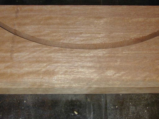
The top rail has an arch cut into the underside. This needs to be cut next. The arch was marked out using a draughtsman's pair of compasses, and then cut close to the line on a bandsaw:
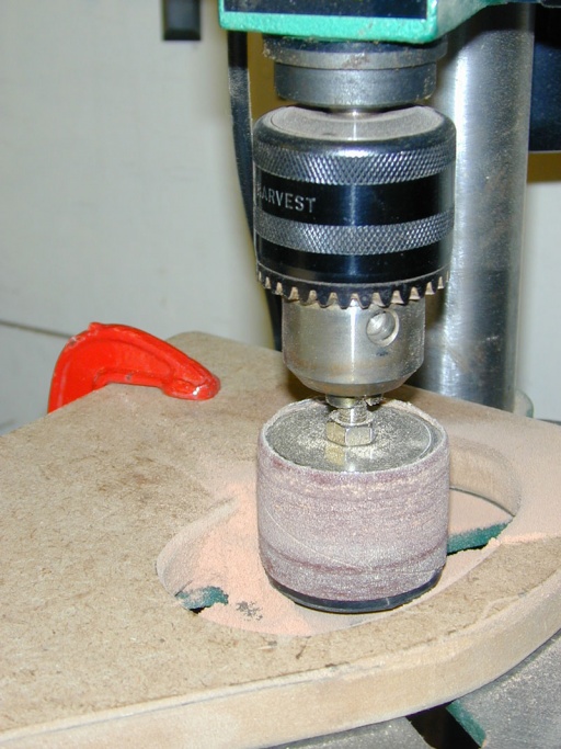
After the cut, the profile was sanded to the line using a drum sander in a drill press:
(I have clamped a bit of MDF with a cutout onto the drill table just so that the sander can reach the bottom edge of the work when sat square on the table)
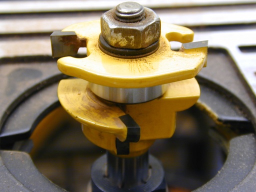
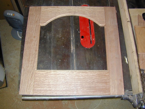
We now have the basic timber sections for the door frame. The next task was to profile the inside edges of the stiles and rails, and the ends of the rails with the Rail and Stile router cutter pair. The bulk of the work is done with the rebate bit that cuts a stepped roundover bead into the front face, and also creates a rebate that will ultimately hold the edges of the raised panel. The top and bottom rail then need a second shaping operation to machine the ends with the matching inverted profile cutter. This will create a secure and snug joint between the frame components:
The frame components were then test assembled:
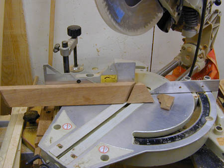
The first assembly revealed that there must have been a slight error in setting of the position of the sliding compound mitre saw (SCMS) when the boards were cut to length, leaving the ends fractionally out of square (an error of well under 1 degree - but enough to be visible on joints like this). To correct this the now profiled ends needed a little rework to recut the mating ends, and get everything lined up. A trench cut on the SCMS to trim the shoulder section of the joints, and a trim of the protruding tenon section on the ends of the rails with a hand plane solved most of the problem. A half round rasp was also used to deepen a short section of the half round profile on the ends of the rails. This then got everything fitting nicely together - although at the expense of making the whole door taper very slightly over its full height. More of this later!
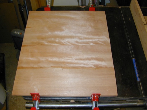
The next stage was to prepare the raised panel. For this a wide board was made by edge jointing four sections of a similar (but only 1/2" thick) wood to that used for the edges. The joints were supported and aligned with a few biscuits, and glued and clamped until dry:
(you can probably tell from the difference in surface lustre that I had already started planing the three board wide panel when I worked out it was actually too narrow, and had to hastily glue on an extra board!)
Once the panel panel has been glued it was planed and sanded completely flat.
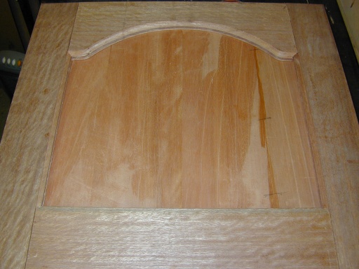
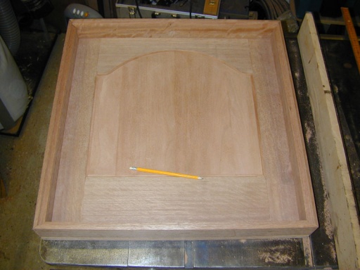
Next the panel was cut to fit. The first stage was to lay the assembled (but not glued) frame onto the panel so that the outline could be traced around the inner edge of the frame and drawn on the panel:
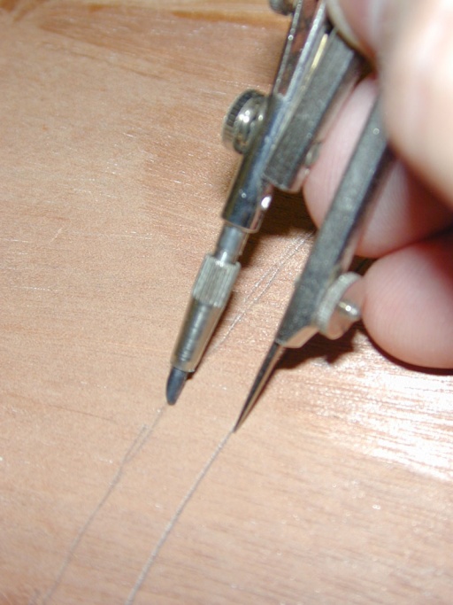
However the panel needs to be a little larger than the frame outline so that the edges can sit in the rebates cut into the rails and stiles. To add this extra material, a second offset line was drawn on the outside of the existing line about 10mm away from it. For the curved part, a pair of compasses were used to follow the outline and draw the offset line:
The straight edge cuts where then made on the table saw, and the curved cut made on the bandsaw. Again the curve was sanded back to the line, making sure it looked smooth and aesthetically "right" to the eye in preference to matching the hand drawn line!
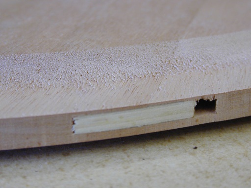
The last job with the raised panel was to add the profiled edge. However after the panel was cut to shape, another problem caused by lack of planning reared its head! The curved cut on the top of the panel had cut through one of the biscuit joints that hold the boards in alignment. This meant that if the raised panel was profiled to the depth originally intended, the biscuit would become visible! The solution was to not cut the raised panel bevel as deeply, and rely on the back cutter of the router bit, to keep the total edge thickness correct.
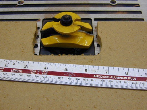
The raised panel cutter is a fairly fearsome looking thing:
This one is so wide that it does not even fit through the aperture in the router table (or its baseplate for that matter), so it has to be installed above the table. To allow for this, a additional table surface is added (cut from some 12mm MDF) so that the big cutter can still be lowered below the table surface. (the cutout in the MDF was simply routed freehand with a straight fluted cutter)
Large cutters like this need a low rotation speed of between 8000 - 12000 RPM. The straight edge cuts can be done with the rip fence in place, however the curved cut needs to be done without the fence. Great care needs to be taken when feeding wood into the cutter to not allow it to snatch, while at the same time making sure if it does, your hands can't get pulled near to the cutter (which would have a finger off in far less time that it takes to say "that's messy!" (dust collection on freehand cuts like that is also a bit hit and miss (well more miss than hit). I clamped the end of the chip collector tube in about the right place, and hoped for the best (and swept up the rest).
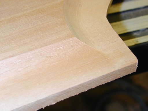
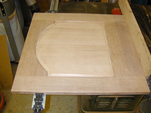
The result was a nice profile edge (although not as deep as designed, and we lost the step effect I had wanted):
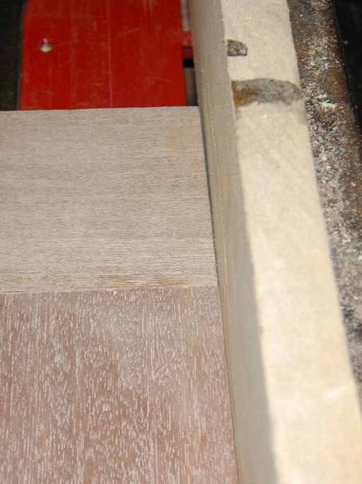
You can see how close to the biscuit this got:
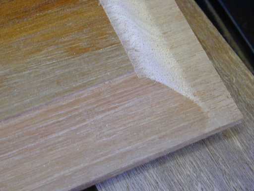
The profile should have looked like that on this test piece:
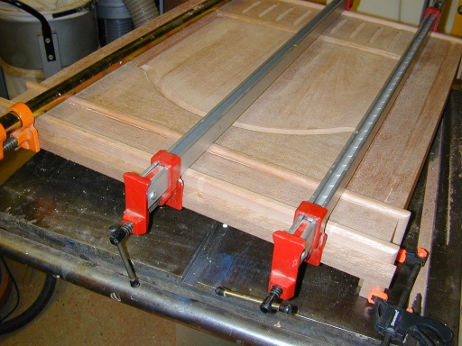
Now the door can be glued up, assembled, and clamped. The glue is only applied to the ends of the rails, leaving the raised panel floating in the frame. Thus if it changes width due to humidity, it should be able to move a little rather than split. (although it might have been better to polish the panel separately to make sure it does not end up bonded in later!)
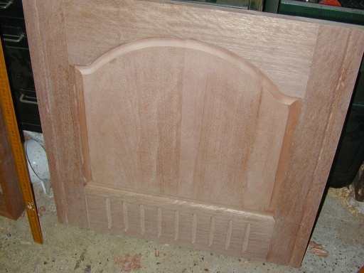
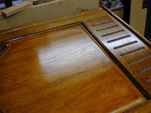
The final stage of the door assembly, is to add the decorative flutes to the front. These are done with a half round "box cutter" in the router. The straight flutes on the stiles are easy - just cut with a fence on the router hand held, or on a table if you prefer. The pattern at the base of the door however called for evenly spaced stopped flutes. For this a custom jig was required:
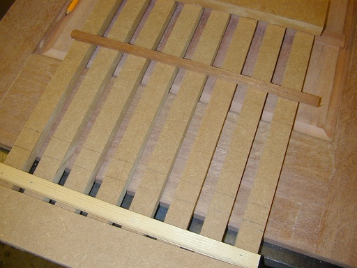
This was made from a number of equal width strips of MDF ripped down on the table saw. These were then glued and nailed (with a pneumatic brad nailer) to a couple of similar cross strips. The spacing was set at both ends using the spigot on a router template guide. This ensured that each slot was of identical spacing, and also would be a perfect fit for the router when fitted with the same guide. The jig was then fixed to the door with a couple of strips of double sided tape (taking care to keep it plumb and centred on the door). A couple of end stops were then nailed in place to limit the top and bottom travel of the router. Finally the flutes were then cut - one between each bar of the jig, and then one either side of the two edges.
The finished door:
Well almost finished as it turns out. You may recall the problem with the "out of square" initial cuts. The combined effect of these on the ends of the stiles, and the fettling needed to get a nice fit on the frame resulted in a slightly less than straight top and bottom edge, and also a door that tapers very slightly (it was 4mm wider at the bottom than the top).
The 4mm error was easy enough to deal with - a straight line was marked out on the outside edge of both rails - tapering 2mm to nothing. Then a few minutes work with a hand plane to plane down to the line.
The second problem posed somewhat more of a challenge in that there was small error, but this time running across a combination of edge and end grain making planing it out rather more difficult:
The simple solution would be to shave off a mm or so on the table saw, but the door was too long for the maximum spacing of the fence on my saw, and secondly both ends of the door are affected, so there is no straight edge to cut against. In the end the solution I used was to fix a Trend clamp guide to the under side of the door, such that it could run along the outside edge of the table. This allowed the door to be run past the blade without needing the saws fence at all:
Back cabinet section
Once the door was finally to size and square, it was possible to make the back cabinet the right size to match it. The edges were cut from the 19mm timber, and a 10mm rebate cut into the back corner of each piece to take the backing timber later. These were then laid out on the top of the finished door, and mitre cut to length:
These where then glued up, and assembled.
(all the mitres in this project were glued using impact adhesive on both surfaces rather than PVA, so that no clamping was required. When extra strength was needed, a 30mm 18g brad nail was shot into the ends of the mitred section, and the nail punched under the surface and filled with Liberon mahogany wood filler. This sands down and stains near enough like the real wood for the holes to vanish).
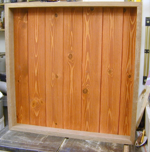
Finally some T&G panels were cut for the back, sanded, and given some red mahogany stain to darken the pine and add some colour. These were brad nailed from the back with a nail at the top and bottom centre of each panel (allowing for a bit of seasonal movement which should be absorbed into the T&G joints). The end panels were ripped to width so as to centre the panelling symmetrically, and these nailed a little more firmly, top, bottom, and at the edges since there will ultimately be used to fix the cabinet to the wall.
Additional Panels and Beads
The bottom of the door is fixed to a base board that encloses the bottom of the cabinet. This was cut from the same 1/2" thick stock as the raised panel, and both top and bottom edges rounded over to create a bullnose effect. The panel was deliberately cut a little wider than the door width and cabinet depth such that the bullnose would create a bead effect on the finished piece.
The was fixed to the base of the door using three No. 20 biscuits. Cut into the door edge with the fence on the jointer, and plunged freehand into the flat of the panel by aligning the edge of the jointer with a line.
A similar panel was produced for the top of the door. There is then a standoff section of approx 2.5" height cut from the 19mm timber that sits above this with mitred corners to create a wraparound look at the top. Finally another section was added above this to create the final bead. This was actually made from a narrower section mitred to go around the corner at the top rather than a full depth panel. Biscuits were sunk in a similar way to assemble all of these pieces (taking care to not line up two biscuits on either side of a 1/2" panel where the slots would meet!). This lot was then glued up and clamped:
Crown moulding
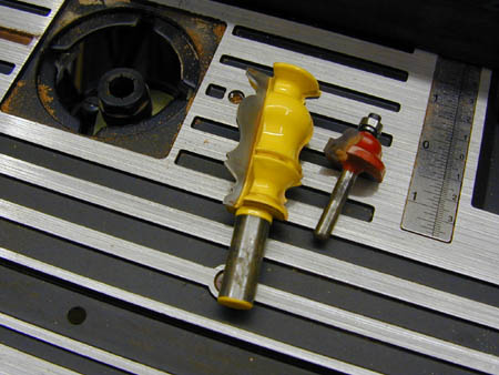
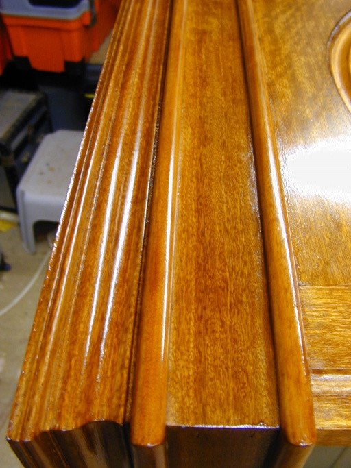
The crown moulding is made from a section of the 19mm timber that was profiled with a Crown Moulding cutter, as seen on the left here:
The sides of this where then bevel cut on the table saw, with the angle set to match that of the bottom flat created by the router cutter. Corner mitres were then cut on the SCMS while holding the moulding at its final mounting angle (this is simpler than attempting to cut a compound mitre).
These are difficult cuts to measure to length correctly, so I cut it a little over size and then "sneaked up" on the final size with additional cuts until the fit looked right.
The mitred sections were the glued up and joined before fitting.
Some holes were drilled through the angled back surface of the moulding, exiting through the base. These were then counter drilled with a larger bit to provide some clearance for a screw head. The base of the moulding was then glued up, the whole thing offered up to position and some Turbogold screws driven down through the holes into the top of the door creating a secure fix for the moulding.
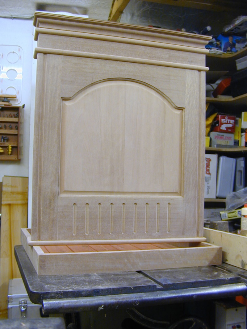
Finally the wood work was complete, and the cabinet ready for finishing:
Finishing and Polishing
The finish used is a traditional French polish, so everything needed to be sanded well! Any rough shaping and levelling was done with a random orbit sander and 80 grit alox paper. Most of the remainder was done with 120 grit on a combination of Random orbit, 1/3 rd sheet orbital, and some hand sanding work. The moulded section was sanded with a 3M foam sanding block that can deform to the shape of the moulding. Bullnoses could be sanded by using the flat base of the orbital and rotating it around the profile.
Once all was getting close to smooth, a manual sand with some silicon carbide wet'n'dry 400 grit came next, and then a final wipe over with some 1200 grit wet'n'dry.
Note that what follows is a description of how I did for my first ever attempt at French Polishing - and it is not a lesson on best practice by an expert polisher! So don't read this in isolation, as there are probably better guides out there!
The polish was made from Garnet shellac dissolved in methylated spirit (it takes a couple of days to fully dissolve with an occasional shake/stir). In all about 200g of dry flakes and 3/4 litres of meths were used.
A traditional "fad" was made from some clean cotton cloth stuffed with cotton waste. Some of the polish was then decanted into a squeeze bottle, and this used to "charge" the fad (by opening it up and wetting the stuffing). (vinyl gloves are a must for this job!).
Initial application
The first application was made by rubbing the fad all over the finished surfaces. Recharging it each time it started to run dry. The finish is absorbed and dries very quickly, and can be re-coated within minutes. A few coats were rubbed all over in quick succession. This seals the surface. It was then allowed to dry for an hour or so, and then lightly sanded with 400 and 1200 grit paper to de-nib anywhere the grain was raised by the initial sealing.
Building up
More coats can then be added to start building up the finish. Working the fad in small circles or figure of eight patterns and covering the surface quickly. Applying reasonable pressure to the fad to keep the polish flowing from it, and maintaining a wet contact with the surface. As more coats are added the colour begins to develop along with the shine. At this stage the fad can start to drag a bit as the new polish partly melts the existing polish. At this point a small amount of boiled linseed oil can be poured into a small dish, and tiny amount applied to the fad from time to time. This helps it move over the surface, and the oil and shellac mixture starts to build the finish. (all in all very little oil is needed - perhaps a thimble full for the whole job). Once a nice shine was obtained, the finish was allowed to harden overnight.
Building colour
Some more polish was added to the squeezy bottle, and this time a small amount of Coloron Peruvian mahogany, and red mahogany spirit based wood dyes were added to the polish. (no more than a thimble full of the plain mahogany, an a quarter of a thimble full of the red to about 200 ml of polish). The idea being to give a very gentle tint, that can be applied in layer to build up as much colour as is required.
No oil was used this time, and straight strokes were initially used to "spirit off" any remaining free oil from the surface. This starts to bring a darker finish to the wood. (the aim here being to match the finish of the clock!)
Once the basic polished surface was in place, a soft brush was also be used to apply polish in difficult to get at corners and then this worked out with the fad.
The inside was initially sealed in the same way as above, however no oil was used in the finishing, and more of the later layers were added with a brush. This yields the same colour and an acceptably smooth finish, but does not achieve the same beautifully smooth effect you get with the proper rubbed finish (mostly because the wood grain does not get filled and levelled in the same way).
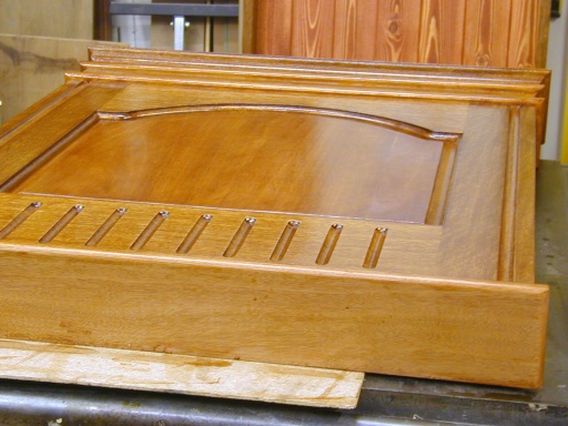
Once the final colour was reached, light fast strokes with a well charged fad help finish off. This was then left for a day before being buffed with a wax furniture polish:
Hanging
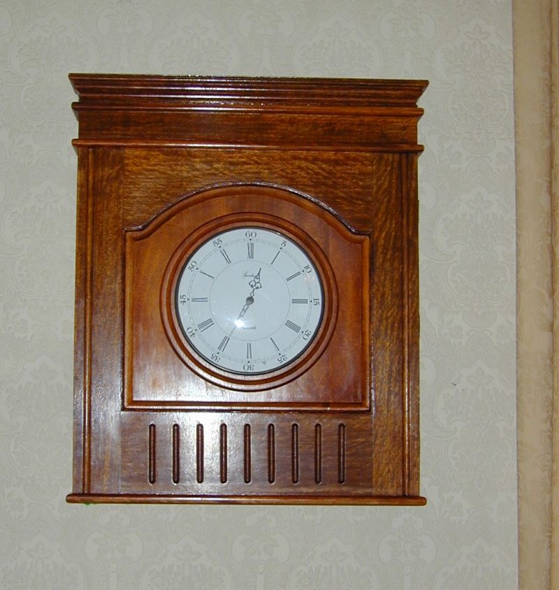
The door was fixed to the cabinet with three brass hinges, and then removed again for hanging. Once the base was securely on the wall (4 two inch screws into wall plugs - one through each corner of the back board), the door could be refixed:
The clock itself simply hangs from a single brass screw driven into the face of the door!
(hopefully all those finger prints will polish off!)
Party Trick
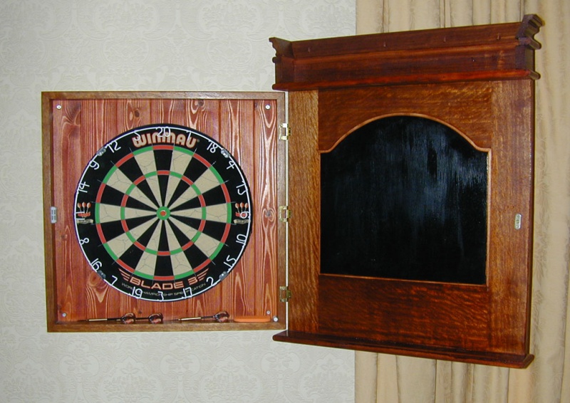
Ah yes, in addition to needing a clock in the lounge, and wanting something nice to look at, the main raison d'être for the cabinet in the first place should now become apparent:
The cabinet conceals a dartboard... Thus circumventing the problem of gaining womanly approval for hanging a dartboard in the lounge!
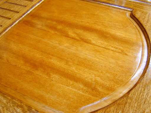
The inner surface of the raised panel door was given a coat of black acrylic paint to make a score keeping blackboard. The lower frame etc makes for a handy storage space for darts etc. A small groove routed in the top face of the inside bottom panel on the door stops the chalk rolling off and makes a handy shelf for the board rubber etc.
The size of the cabinet section was made at about 24" square to allow some aiming latitude for the less accurate dart players (cough women cough!)
