Difference between revisions of "Classic large bookcase and cupboard"
m (→Base Units) |
m (→Doors) |
||
| Line 87: | Line 87: | ||
==Doors== | ==Doors== | ||
| − | The doors were made from 75mm wide PAR softwood for the rails and stiles, | + | The doors were made from 75mm wide PAR softwood for the rails and stiles, and the raised panel made from a number of the same strips glued up to make wider stock (it was easier to glue up enough for three panels in one go, and then rip it to width on the table saw after. |
The door assembly was done using a rail and stile profile bit set on the router table as shown for [[Cabinet_clock#The_Door|this door]] | The door assembly was done using a rail and stile profile bit set on the router table as shown for [[Cabinet_clock#The_Door|this door]] | ||
Revision as of 06:22, 21 June 2014
Introduction
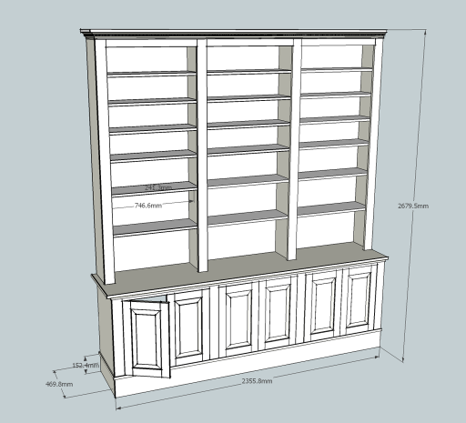
This article is a quick overview of the build of a very large (around 8' wide and 9'6" tall) bookcase and cupboard combination.
(click the photos for larger sizes)
Design
This particular piece was going into a lounge on the rear wall. Its main function will be to hold books, DVDs, and other stuff. The design is along classic lines and is intended to be somewhat "architectural" and in keeping with a Victorian style property with high ceilings.
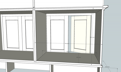
To keep the design simple and also to make the piece transportable from the workshop to the final installation, it needed to be of a modular design. The design is based around six boxes. Three forming the lower cupboards, and three for the shelving units. All of the decorative finish work is applied as a face frame to the boxes after they are built.
Materials
There is a quite substantial amount of material used in this project. To keep the costs down, mostly sheet goods are used to build the bulk of the project. In all there were 3 sheets of 19mm MDF, 3 sheets of 9mm MDF, 3 Sheets of 19mm ply, and then a substantial amount of 4x1" PAR softwood.
Material Preparation
My workshop is too small to easily feed 8' sheet materials into the table saw, hence a sawboard was used with a hand held circular saw to break down the sheets into manageable sections that could then be cut on the table saw.
Plinth
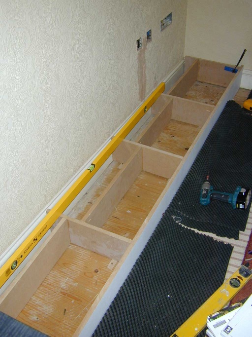
The plinth is separate from the rest of the project, and is intended to be installed and levelled first before the rest of the project is added on top. Hence 19mm MDF strips around 150mm tall were cut to form the framework and the face of the plinth. The sections simply joined together with butt joints held by pocket screws. There is a baseboard made from 19mm MDF to sit over the plinth. This was edged with softwood strips that were routed with a bullnose profile to make an attractive edge to the MDF.
Base Units
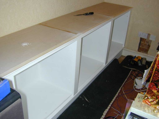
The base unit boxes are made from 19mm MDF, and the joinery is about as simple as it can be. Rebates were cut in the top and bottom inside edges of the two sides, using a stacked dado blade in a table saw. Then an additional dado was cut in the inside rear edges of the sides as well as the top and bottom to accommodate the 9mm MDF back. The joints were glued, and then pined with 30mm brad nails using a pneumatic brad nailer. The back was cut squarely and once fitted and nailed in place, pretty much guarantees that the box section will also be square.
Once the three base unit boxes were complete, the face frames were made up from the PAR softwood forming 75mm wide mullions and rail. These were fixed to the boxes from the inside using pocket screws.
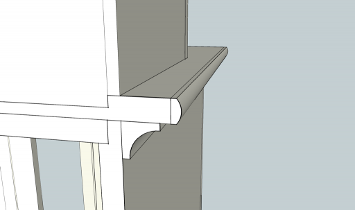
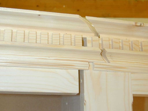
The final stage was to fit a 30mm Scotia (cove) moulding around the top of the cabinets and face frame to form the decorative reveal under the worktop that would ultimately cover the three cabinets. The moulding was made using a 3/4" cove cutter on the router table. The moulding was fitted in sections such that the boxes could be separated for transportation. Each section joining to the next with a scarf joint to attempt to make the joint less visible. Since only one edge of the cabinet would be exposed (the other would be against a wall), the moulding only needed extended along one side and the front.
Shelving units
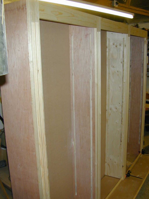
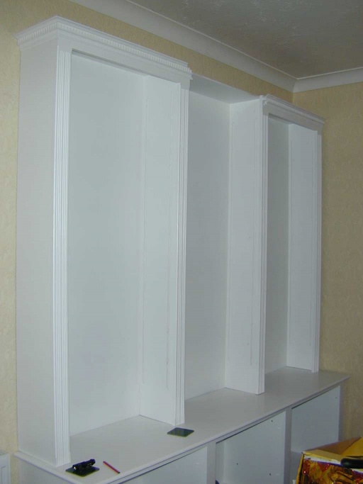
The shelving units were almost a repeat of the bases units, except there was no "base" to these - it was left open, and the 9mm MDF top was simply planted on top of the back and sides. The sides were cut from 19mm ply. Hardwood faced ply was used for the left and right cabinet, and a structural softwood ply for the centre one - the different materials really just being used to see which gave the better results. It transpires the softwood ply is lighter and easier to work and also finishes nicely, but it lacks the perfect flatness of the hardwood ply.
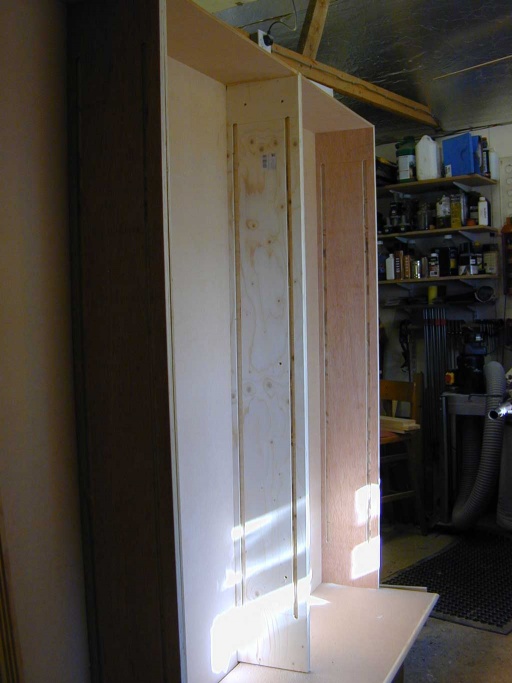
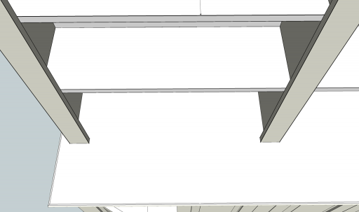
The back edge of each side had a rebate cut to accommodate the MDF back. (here I made the slight mistake of marking out one side and then transferring the markings to the other sides using a square. Alas this ultimately yielded six right hand sides... I had to then recut the rebate for the back onto the front edge of three of them!). The inside faces had some 5/8" dados routed into them to take some shelving bracket strips.
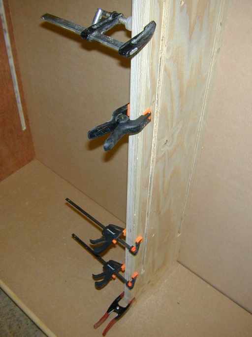
Fixing the error created by rebating the wrong edge - softwood filling strips were glued in place and then trimmed flush
Once the three boxes were complete, they were placed together on a makeshift plinth, and the centre box screwed to the the ones either side.
Face frames
The face frames for the shelves are slight unusual since they need to present three consistent openings, but at the same time the left most mullion must end flush with the left side and the rightmost must be flush with the right side.
Hence the positioning on the shelf cabinet sides is not the same for each cabinet.
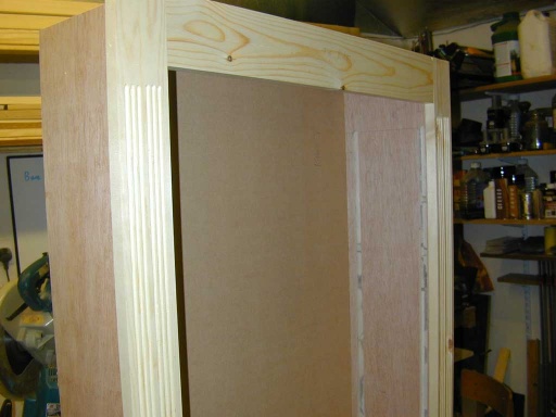
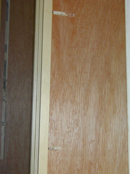
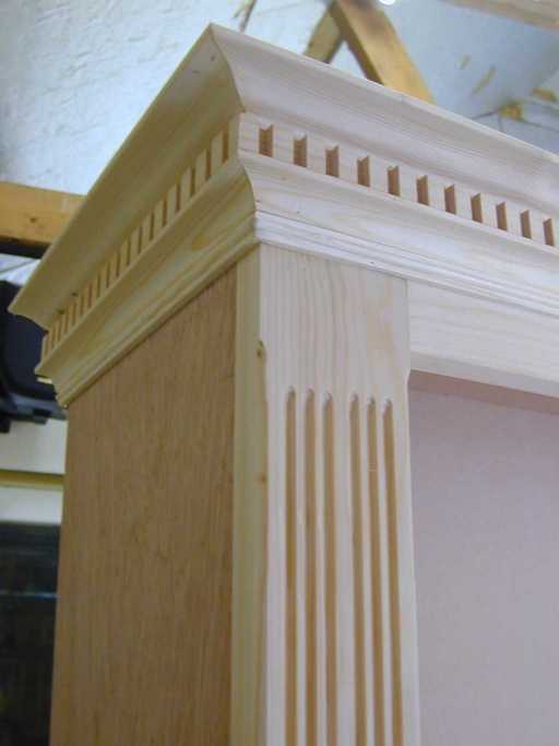
The face frames are made from the same 75mm wide PAR as used for the base units, except this time a beading cutter is used in the router table to add some decorative flutes to the fronts of the verticals. A stopped chamfer was also added to the edges, but leaving the corners and ends with sharp corners.
The fixings for the face frames were done in the same was as for the base units with pocket screws, however since these would be far more visible, the fixings were concealed by doing them on the outer edges of the cabinet sides where ultimately they would be hidden by the adjacent cabinet or the wall. The only exception to this was the left side of the leftmost cabinet where both inside and outside surfaces of the cabinet side would be visible. For this one, the frame was glued and biscuit jointed to the front of the cabinet box.
Face frames are only actually fitted to the left and right cabinets. The centre one simply slots behind the overhanging edges of the frame from the cabinets to either side.
Top moulding and cornice
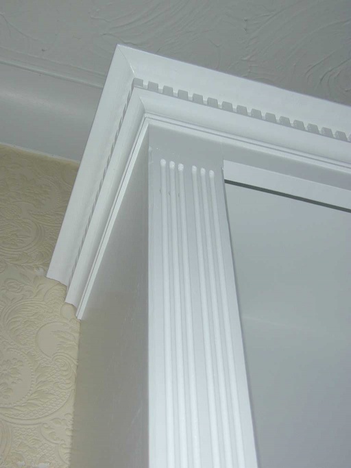
Once the frames were fitted, attention could be turned to the top moulding. This was intended to be quite elaborate and was build up from four separate sections.
The top section was cut on the router table using a panel raising cutter (in fact the same one used to make the raised door panels later). This cuts an ogee relief on the edge of a section of timber. The back of the moulding was glued and then pinned in place with a 23 gauge headless pin nailer (these leave a tiny hole that is practically invisible and can easily be filled or painted over).
The second section was a dentil moulding. This was cut with a dado stack in the table saw set for a 1/4" cut. A fence was screwed to the table saw mitre gauge, that reached right past the blade position, and then a 1/4" notch was made in the base of this fence, 3/8" inch from the right hand side of the dado blade. A small 1/4" section of wood was then glued into the notch to act as a guide stop.
The dado blade was set to make a cut 1/4" deep. To cut the moulding, a 24" length of 5x1" PAR was slid up to the guide peg and the first dado cut into the underside of the timber. The notch created was then placed over the guide peg, and the next notch cut. The process can then be repeated with each new notch creating the guide to space the next notch. The result, a series of perfectly spaced 1/4" wide notches with 3/8" spacing all along the timber. Once this was complete, it was ripped lengthways into 3/4" wide strips. The strips were then glued and pinned under the top section of moulding.
The third section was another bit of 30mm Scotia made in the same was as that used for the trim on the base units. This was set to just batch the depth of the dentil. That was also glued and pinned in place.
The final section was a read moulding. Cut onto the edge of a plank on the router table. The moulding then ripped off the edge of the plank on the table saw. This was repeated a few times until enough moulding was cut. The thickness of the moulding was carefully set so that it matched the thickness of the bottom edge of the Scotia moulding - thus when placed together the almost appear to flow into each other and the join vanishes.
Again the moulding sections were designed to separate at the cabinet junctions. Scarf joints being used again to hide the joins a little. The centre section cornice was fixed to the top face frame section for the centre cabinet - this is not actually attached to the cabinet at all, and is simply fitted to the edges of the left and right face frames once the cabinet is assembled in place.
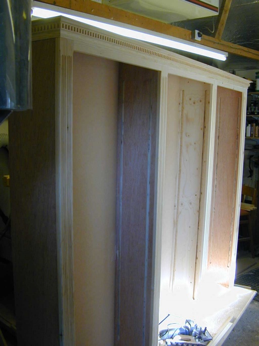
The final result built up in the workshop as a test assembly
Doors
The doors were made from 75mm wide PAR softwood for the rails and stiles, and the raised panel made from a number of the same strips glued up to make wider stock (it was easier to glue up enough for three panels in one go, and then rip it to width on the table saw after.
The door assembly was done using a rail and stile profile bit set on the router table as shown for this door
Shelves
There are 18 shelves for the top units and 3 wider ones for the base units. These were all cut from the 19mm softwood ply, and edged with pine strips. The top and bottom of each strip softened with a 6mm roudover bit in a trim router.
Worktop
The final section required was a large single bit of MDF with bullnosed softwood edges for the worktop. To give a little extra rigidity to the top cabinets, the backing sheet of MDF one them was cut 1/2" longer than the sides, such that the back protruded below the bottom of the cabinet. A matching slot was cut out of the back of the worktop with a handheld router to accommodate this lip. This creating a way for the top cabinets to register more positively on the worktop and also hide any unsightly line or gap that may have otherwise been visible.
Finishing
First everything that was going to be painted was sanded down through the grades to 240 grit. An acrylic primer suitable for MDF was then applied with an HVLP spray gun. (some of this being done outside due to lack of space in the workshop!). The one or two coats of a Johnstones acrylic fast drying satin finish applied on top. Where possible this was also sprayed, but since this had to be done inside (the bug collection that got stuck in the primer, encouraged me not to repeat that trick for the final finish!) some of that had to be applied with a 4" sponge roller since one had to work on small sections at a time. The surfaces were de-nibbed with a 240 grit sponge sanding pad between coats.
Even though only the visible surfaces were painted, the sheer surface area of all the sheet materials resulted in needing nearly 3.5L of primer, and 3L of top coat (which was getting on for £80 worth of paint). This exercise also highlighted how nice it would be to have a dedicated finishing / spraying room for large projects like this!
Assembly
Plinth
A section of carpet was cut out from the area where the furniture was to be installed (since this is in effect built-in, any carpeting and decorating in future can go round it!). The plinth was then assembled from sections and the length cut to match the units base board. The facia of plinth (which had been pre-painted by this stage) was finally fixed to it with pocket screws from the inside before the base board went on. The ends of the facia being scribed round the profile of the skirting board in the room.
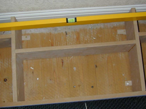
To get the plinth level, I cut some wedges from some oak offcuts, and then used these to get the plinth level. The wedges being placed over where the joists run under the floor. The wedges were fixed in place with some self drilling screws to stop them moving or working loose.
Once the plinth was in and level the baseboard was placed on top and screwed to the plinth.
Cupboard units
The three cupboard units were then brought in, screwed together, and finally screwed down to the base board.
The worktop board was then placed on top, and fixed by some screws from the inside of the cupboards.
The shelf units
Each of the shelf units were then installed and positioned. The inert section of the cornice for the centre cabinet was fitted last, and then all the cabinets screwed together.
Some metal L brackets were also installed at the very top of the cabinets to retain them against the wall, just for safety.
Fitting out
Next the shelving strips could be fitted, and the doors hung. The shelves could start being loaded into the cabinets:
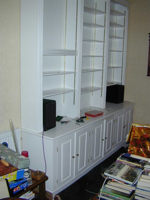
(one sacrifice was there was no longer space for my rear effects speakers to stay on their Atacama SE24 stands, and these had to be moved to the worktop of the cabinet. (ultimately the wires were also fed through it, and a hole drilled through the worktop to accommodate them)
Result
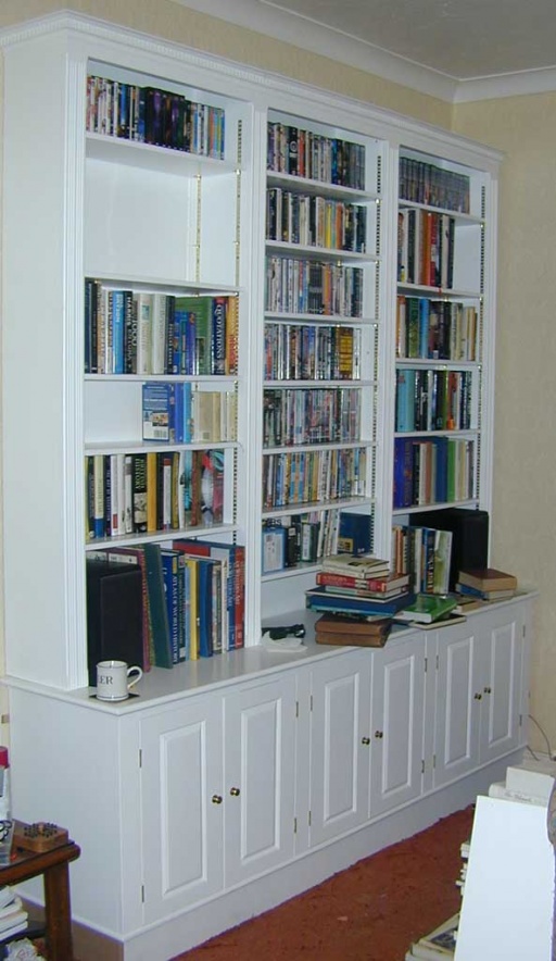
After several weeks of work building and finishing the unit, it was finally time to start filling it!
All in all quite pleased with the result. It manages to look sufficiently architectural:
when you catch it at the right angle, and it holds plenty.
(lets just hope the floor is up to the weight, since the whole lot is probably pushing 1/2" a ton fully loaded!)
