Difference between revisions of "Dovecot / Bird house build"
(First draft - not proof read - might be a load of cobblers!) |
m (Re-scaled images) |
||
| Line 6: | Line 6: | ||
So I thought its worth a look. | So I thought its worth a look. | ||
| − | [[image:DovecotKnackeredOriginal.jpg| | + | [[image:DovecotKnackeredOriginal.jpg|512px]] |
"What's wrong with it?" | "What's wrong with it?" | ||
| Line 44: | Line 44: | ||
The Roof members are cut as traditional rafters with "birds mouth" joints a at the eves. A smaller hex ring was made up to act as a ring purlin. | The Roof members are cut as traditional rafters with "birds mouth" joints a at the eves. A smaller hex ring was made up to act as a ring purlin. | ||
| − | [[image:DoveCotSkelleton.jpg| | + | [[image:DoveCotSkelleton.jpg|512px]] |
===Cladding=== | ===Cladding=== | ||
| Line 68: | Line 68: | ||
A template was made up from the bird entry holes: | A template was made up from the bird entry holes: | ||
| − | [[image:DoveEntryHoleTemplate.jpg| | + | [[image:DoveEntryHoleTemplate.jpg|512px]] |
This was fixed to the side with a couple of dabs of hot glue, And a router fitted with a template following bit used to cut the holes. | This was fixed to the side with a couple of dabs of hot glue, And a router fitted with a template following bit used to cut the holes. | ||
| Line 79: | Line 79: | ||
The same doves tail theme was used for the landing pads for the birds. | The same doves tail theme was used for the landing pads for the birds. | ||
| − | [[image:DoveTailPadBlank.jpg| | + | [[image:DoveTailPadBlank.jpg|512px]] |
Three bits of old pine were glued up to give a three inch thickness. A paper template made and traced on in the same way, and the rough shape cut on a bandsaw. The final finishing to the line being done on a oscillating bobbin sander. Once we had a nice thick block in the right shape, this was simply re-sawn into six separate pads. A small bit of door architrave (cut at and angle) was used to strengthen the joint to the walls, and add some more decoration. Each perch was simply glued and nailed in place. | Three bits of old pine were glued up to give a three inch thickness. A paper template made and traced on in the same way, and the rough shape cut on a bandsaw. The final finishing to the line being done on a oscillating bobbin sander. Once we had a nice thick block in the right shape, this was simply re-sawn into six separate pads. A small bit of door architrave (cut at and angle) was used to strengthen the joint to the walls, and add some more decoration. Each perch was simply glued and nailed in place. | ||
| Line 109: | Line 109: | ||
First with the old one lurking in the background: | First with the old one lurking in the background: | ||
| − | [[image:Dovecot1.jpg| | + | [[image:Dovecot1.jpg|512px]] |
And the second showing more of the detail at the base of each wall. | And the second showing more of the detail at the base of each wall. | ||
| − | [[image:Dovecot2.jpg| | + | [[image:Dovecot2.jpg|512px]] |
Revision as of 09:52, 17 June 2015
This is not so much a "how to" article, but more a "rough idea" one! The inspiration for this project came from a request from a friend to help him "restore" his Dovecot. As is often the case, the restoration soon turned into a rebuild!
Introduction
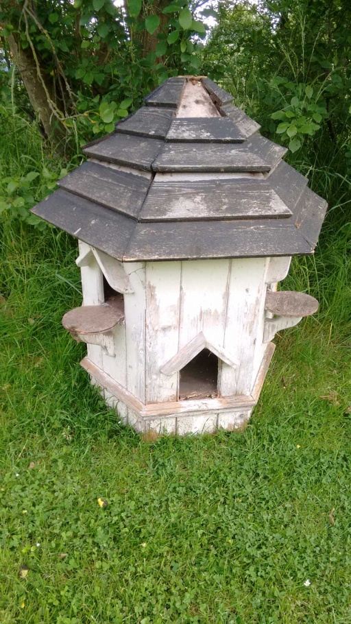
So a mate says "If I brought round my Dovecot, could you mend it?"
So I thought its worth a look.
"What's wrong with it?"
"It got left outside!"
(which one would have thought was not unexpected for a bird house you are supposed to mount on a pole in the garden)
So did a bit of a post mortem on it... yup its pretty shagged beyond sensible repair. Not helped by its original builder starting with a subframe of non water proof ply, before giving it a roof that would be as effective at keeping the rain out as a colander!
So I suggested that I use it as a rough pattern, and build a new one from scratch.
Materials
This was a built it from whatever is laying about build. There was some exterior grade OSB that we could use for the frame, and about 4m of 4x2 CLS softwood that could be re-sawn into structural timbers and cladding.
Building it
The first stage involved ripping down some 4x2 into approx 1.25" x 1" timber to use as the frame.
All you think about is hex
The original was hexagonal in shape and that did not look too bad. It made for six reasonably generous boxes on two levels. So I decided to stick with that basic concept.
The first stage was carefully setting the mitre saw to cut a 120/60 degree angle. And and end stop to set the length. I then cut 24 pieces, or enough to make 4 "rings" that would form the overall shape of the building.
Each of the rings were assembled with glue (Titebond II - waterproof) and lots of 30mm 18g brad nails. (ultimately these will make nail targets for holding the cladding on)
Three OSB floors were cut to match the size of the rings. These were cut on the table saw with the mitre gauge running in the slot on the table.
Ground floor
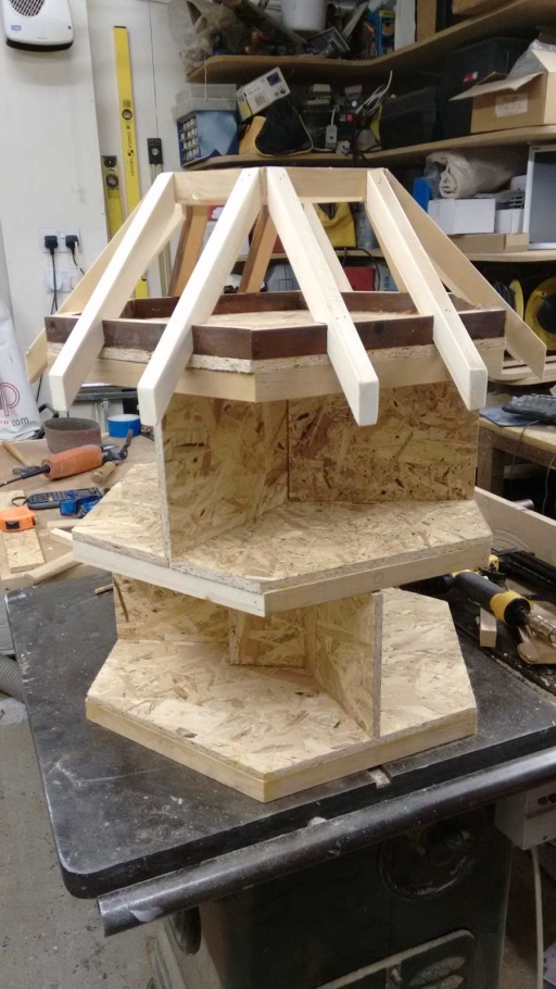
The edges are about 14" long. The height about 10" The centre of the floor has a 4x4" hole cut in it, ready to accept the support post, and internal walls are built round this (hence the post will protrude the full height of the ground floor - with the top of it hitting the underside of the first floor). The walls were glued and nailed next.
Second floor
Same as the ground, but without the post hole. The tops of the wall below needed to have the corners notched out so that the hex ring of the floor could drop down far enough to allow the ground floor ceiling to sit on top of the walls.
Roof
A repeat of the first floor, with an additional hex ring added to give more elevation to the roof, and act as a wall plate.
The Roof members are cut as traditional rafters with "birds mouth" joints a at the eves. A smaller hex ring was made up to act as a ring purlin.
Cladding
More 4x2, this time resawn into 4" wide and 10mm (ish) thick planks. Planed on the jointer, and then run through the thicknesser to get a uniform set of boards. A rebate was cut on the back of one side, and the front of the other using a dado set in the table saw (sunk into a sacrificial fence) this creating a simple "shiplap" profile.
A final pass on the jointer with its fence set at 45 degrees, added a bevel to one side of the board to create a shadow line at each board joint in the final panel.
The boards of each panel are not joined to each other, but are simply nailed in the middle of each board to the framework, and the next board added (with a little space to allow for seasonal movement) the added and nailed beside it. The shiplaps cover the gaps. Working round the whole building in a clockwise direction until you get back to the start.
The edges needed to be ripped at a 60 degree angle on the table saw, and any overhangs planed flush once nailed on.
This resulted in a hexagonal clad "cylinder" with no entry holes or decorative features.
Roof skin
The roof skin was simply cut from more OSB. Having discovered that 3D geometry is actually quite difficult to get right on paper, I decided to resort to every engineers trusted aid: CAD (yup, Cardboard Aided Design ;-) A cardboard template made it easy to cut the roof panels. Rather than worry about trying to tilt the blade to get the right edge angle, it was easier to cut the edges square, and then use the jointer with its fence at an angle to add the bevel after.
The roof panels were then taped together on the bench flat, and the bevels filled with glue. The (gaffer) tape held everything together long enough to pick the roof up into its final "conical" shape, and join the remaining two edges.
Once the roof was dry, it cold be dropped onto the roof frame as a "lid" and nailed on. (a very slight error in sizing meant it did not sit completely flush all round. So I ran a small battery hand held circular saw up one hip ridge of the roof. The width of the kerf of the blade removing enough excess material to adjust the fit. The boards were then nailed and glued back together at the cut.
Cutting holes
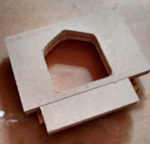
A template was made up from the bird entry holes:
This was fixed to the side with a couple of dabs of hot glue, And a router fitted with a template following bit used to cut the holes.
I decided to use a "doves tail" style shaping for the decorative details. So made up another template (drew half with a flexi curve, then folded and traced the mirror half, before "tattooing" the contour onto some MDF with a sharp point through the paper pattern).
This template was first used freehand to draw the profile on the bottom of each wall. The bulk of the wast was then cut away with a jigsaw. Finally the template was hot glued back into place, and the router used with a trim bit to give a clean and accurate edge.
Launch pads
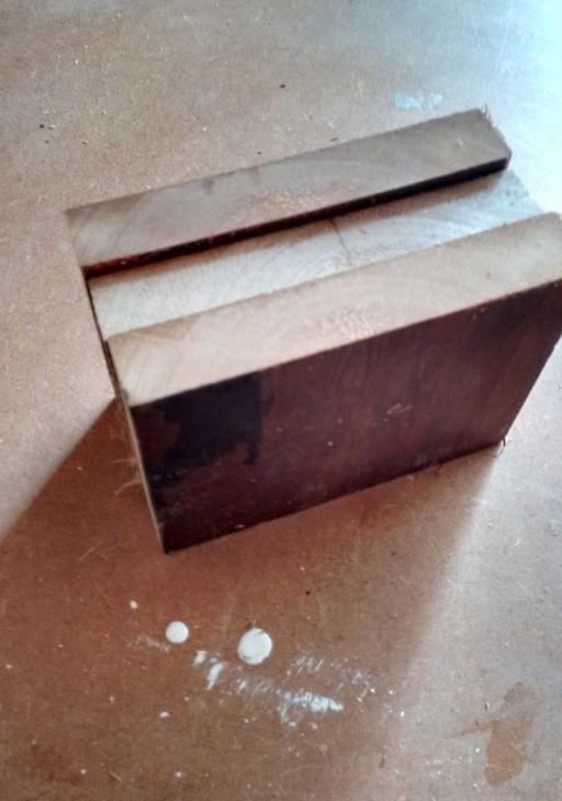
The same doves tail theme was used for the landing pads for the birds.
Three bits of old pine were glued up to give a three inch thickness. A paper template made and traced on in the same way, and the rough shape cut on a bandsaw. The final finishing to the line being done on a oscillating bobbin sander. Once we had a nice thick block in the right shape, this was simply re-sawn into six separate pads. A small bit of door architrave (cut at and angle) was used to strengthen the joint to the walls, and add some more decoration. Each perch was simply glued and nailed in place.
Finishing
First job fill al the nail holes and dings (the 4x2 was reused and had things nailed to it in the past) with two part epoxy wood filler. Sand down to 120 grit.
Paint - using a Johnstone's acrylic internal / external self undercoating semi gloss. Three coats in all.
The interior of each bird box was given a coat of waterproof lacquer.
Roof tiling
The roof was going to be felted, but in the end there was not quite enough of that spare. So some spare fibre cement "slates" were clamped up into a block of five, and cut into 4 strips about 3" wide with a large angle grinder.
These then had to be mitred individually at each end as they were fitted (diamond disk in a 115mm grinder, with a vacuum hose setup on a support to catch the dust from each cut as it was made). The flashings were made from real code 4 lead of a roll 6" wide. This was cut down the middle to make 3" wide strips. These were first folded at one end and the edge nailed to the roof with type A 16mm staples. Once the slates were in, these were folded over first to the left, then back over themselves to the right - thus covering both slate edges with a single piece of lead.
Each slate was tacked in place with hot glue, (and a generous bead used to seal the lower edge of one against the top edge of the other with a small overlap) The slates were fitted from the bottom first. A couple of holes drilled to allow retaining screws to be added through the top if each slate, and then the slate above was glued over the first one hiding the screws.
As a final "to be sure" measure some clear silicone sealant was injected into all the roof edge gaps under the lead.
A lead cap was then made to fit over the top wood plug that finished the roof (and which was also threaded to take the finial).
(The finial was a bit of old table leg, with its end reshaped on the drill press using a rasp and some sandpaper!)
The result
The final result:
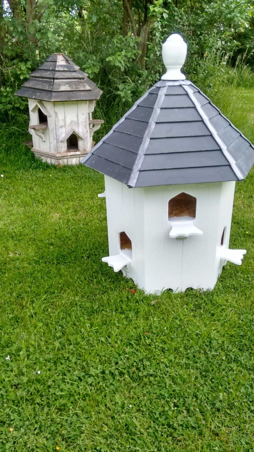
First with the old one lurking in the background:
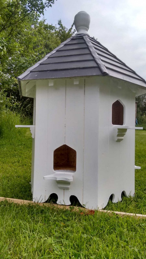
And the second showing more of the detail at the base of each wall.
