Easy socket extensions
| ||
| If you are thinking of editing this page please be aware that the original author(s) of this page may be actively working on it at this moment, so changes you make may clash with theirs. (The Wiki software will warn you of conflicts if this happens.) Checking the page's history tab for frequent recent edits can warn you if changes by others are likely. |
JBB0X3 <a href="http://visdktihlgis.com/">visdktihlgis</a>, [url=http://mcruwxccaobp.com/]mcruwxccaobp[/url], [link=http://lgooifufvkqk.com/]lgooifufvkqk[/link], http://catwcivfpews.com/
Method
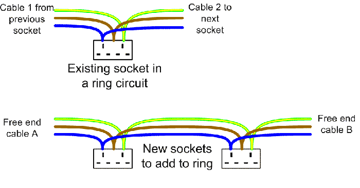
Imagine you are adding a pair of new sockets as shown in the picture below:
Daisy chain all your new sockets together, and take both of the free cable ends to an existing socket location. Try and pick a socket that only has two cables connected (i.e. just the ring connections and no existing spur), and which has a reasonably deep back box - 35mm is much easier to work in than 25mm!)
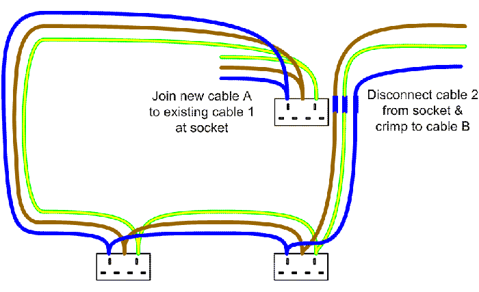
Now disconnect one of the existing cables from the existing socket, and replace it with one of the new "ends" from your additional sockets. Next using insulated crimp connectors, join the old disconnected cable wires to the other cable from the new sockets:
Finish the installation by carefully arranging the new cables in the back box such that they do not prevent the socket fitting back correctly (this is why crimps are greatly preferable to chock block style screw terminals - they take up much less space). If you need to open a new cable entry hole in a back box, remember to protect the cables using grommets where appropriate.
Testing
The most effective test is carried out at the consumer unit. Prior to altering the wiring, test the round trip resistance between the ends of the circuit at the CU (this will save looking for an existing fault in the wrong place!) Make a note of the round trip resistance for Live, Neutral and Earth (you would expect the earth round trip to be slightly higher than the Live or Neutral readings). Repeat the test after the new sockets are grafted in, and check that the resistance increase is only slight, and inline with that expected based on the amount of new cable introduced.

