Difference between revisions of "Extractor fan wiring"
m (typo) |
m (typos) |
||
| Line 35: | Line 35: | ||
===Fans with a built in humidistat=== | ===Fans with a built in humidistat=== | ||
| − | Humidistat fans are triggered by the level of | + | Humidistat fans are triggered by the level of moisture in the air. Thus they respond when the air gets steamy, and run until the humidity level is reduced. Fans are available with a built in humidistat, or alternatively, an external humidistat can be connected to other types of fan. |
| − | These can be simply connected to a permanent live and neutral (via an isolator) ins the same way as a basic fan (see above). They will then run entirely under the control of the built in humidistat. | + | These can be simply connected to a permanent live and neutral (via an isolator) ins the same way as a basic fan (see above). They will then run entirely under the control of the built in humidistat. |
===Fans with timer and humidistat=== | ===Fans with timer and humidistat=== | ||
Revision as of 11:32, 20 February 2016
This article describes how mains powered extractor fans of the type often found in bathrooms and shower rooms can be wired.
Introduction
Extractor fans in bathrooms are frequently powered from a lighting circuit. This is because many include a "run on" capability that is triggered by the operation of the light switch, and it is not permitted to have a device powered from two separate circuits. Also UK bathrooms have traditionally not included power sockets, so it is common to not have any general purpose power circuits available in the room. Fans in other locations may be more commonly powered from a fused spur taken from a socket circuit.
This article describes the wiring schemes for a number of fan types and applications.
Basic requirements
Note also there are additional rules that apply to Bathroom electrics (and swimming pools & saunas), and these must be followed for all fan installations in these locations. Kitchens are no longer classed as special locations, and so follow normal wiring practice rules.
Fans (especially those that may be operated by automatic controls) should be fitted with an isolation switch that will interrupt all live conductors (i.e. including neutral). This is to allow safe cleaning and maintenance of the fan. If the isolator is not visible to the person working on the fan, then it should also allow a facility to be "locked off" to prevent someone re-enabling it while work is being carried out (many isolators now include this capability as standard).
Some fans may also need additional fused protection (e.g. at 3A) even when only connected to a 6A lighting circuit. So you may need to include a fused connection unit in the feed to the fan. Consult the manufacturers instructions.
Wiring plans
The best place to take an electrical feed for a fan from is often a ceiling rose or junction box where the main lamp fitting is connected. This has the advantage of having all the connections required available in one place. Normally a three core and earth cable would be used for this.
Basic fans
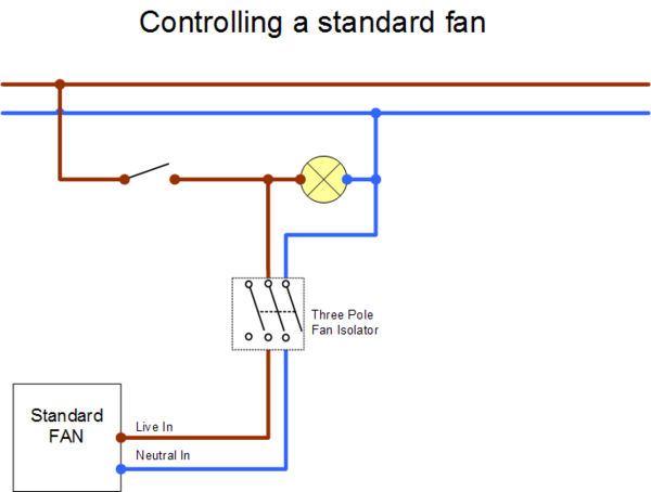
This is the easiest to wire. It is either run from a separate on / off switch (typically a pull switch) or perhaps a delayed action switch such as a Vacuum time lag switch, or can be connected in parallel with the lamp in the room such that it comes on whenever the light is on. Unlike other fan installations, it does not need a permanent live connection.
This wiring plan will simply run the fan when the room light is on. It can also be adapted for separate switching if required. Options include a manual pull switch, and a Vacuum time lag switch. The time lag switch will allow the fan to be manually started, but then run for a pre-set time. These manual switches have the advantage of needing no power themselves, and so will run with typical light switch wiring, and are compatible with all lamp types. (electronic time switches often need to bleed a small amount of power through the lamp to self power. These often cause odd behaviour with compact fluorescent, LED and other very low energy lamps). Note the use of a three pole isolator is not required in this case, but is quite often convenient, since the switches are often marked as fan switches and include a lockout capability.
Fans with a timer
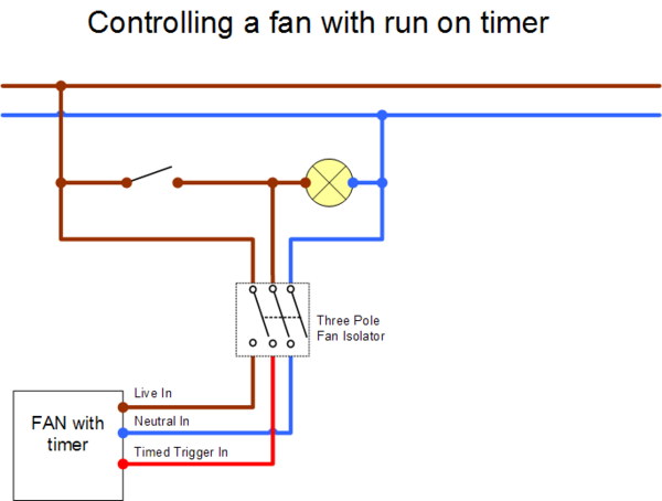
This type of fan is very common. It will typically start operating when the light is switched on, but then continue to run for a pre-set time after the light is turned off. Thus "clearing the air" in the room.
More sophisticated examples may include a "delayed start" facility where it does not start up until the light has been on for a certain length of time. So the fan would not run for short trips to the bathroom, but would start running for longer ones. These are ideal for installing in places like en-suite bathrooms where fan noise might be undesirable at night.
Some fans even include a "timed refresh" mode, where they can be set to run periodically through the day - at pre-set intervals and durations. This is intended vent stale air from rooms with no natural air circulation.
This plan is ideal for timer fans triggered by the lighting circuit. The three pole isolator switch allows for interrupting both the switched as well as the permanent live and neutral connections.
Fans with a built in humidistat
Humidistat fans are triggered by the level of moisture in the air. Thus they respond when the air gets steamy, and run until the humidity level is reduced. Fans are available with a built in humidistat, or alternatively, an external humidistat can be connected to other types of fan.
These can be simply connected to a permanent live and neutral (via an isolator) ins the same way as a basic fan (see above). They will then run entirely under the control of the built in humidistat.
Fans with timer and humidistat
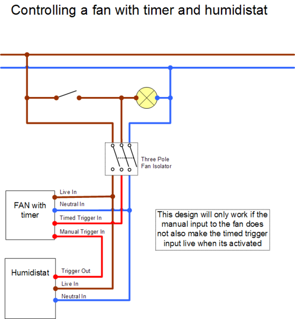
In some cases it might be desirable to include more than one type of control for a fan. Say to have timed run on operation for clearing smells from a bathroom, and additional humidistat control to reduce moisture and dampness in the room at other times.
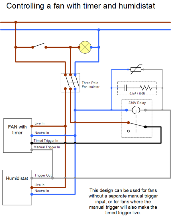
This is the simple version of the circuit. Note that the alternative version below may be required if you find that you humidistat also turns on the room light when it runs the fan.
The more complicated switching arrangement disconnects the link to the switched live of the lamp when the humidistat is active. (you can also achieve the same result by using a double pole light switch, and using the second pole only for triggering the fan - however that is less easy to retrofit in many cases since the wiring required will not be in the drop to the wall switch).
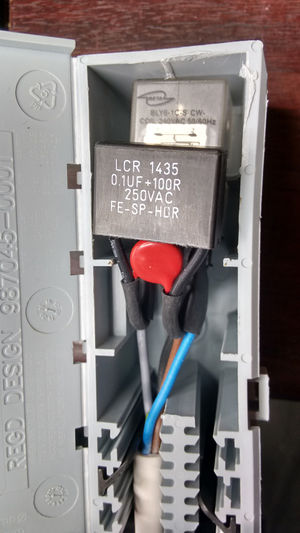
Since the above circuit includes a relay, additional transient suppression is included to prevent large voltage spikes generated when the relay coil is energised or powered off. This will protect the electronic circuitry on the fan. Consult the manufacturers instructions about what level of spike or transient suppression is required. (many will stipulate that protection is also required if the fan shares a circuit with traditional linear fluorescent lamp fittings, since these have an inductor used as a ballast, and this may also generated voltage transients).
Using relay controls
The above photograph shows a mains operated relay wired to a 4 core flex (connections soldered and heat shrunk to the tag terminals on the relay). Since the relay coil may produce unwanted voltage spikes into the circuit wiring (which may damage the electronics in some fan units), some effort has been made to suppress these. In this case, a common 0.1uF/100 Ohm RC mains input suppressor, as well as a 250VAC Metal Oxide Varistor (MOV) transient suppressor were used in parallel. These were assembled into a wago box. The whole unit is intended to be lost in a building void somewhere (i.e. near the fan or its switch), and connected to the circuit via its attached lead.
Commonly the isolator switch makes a good location to include all the necessary terminations.
