Installing a concealed shower mixer valve (retrofit)
This article describes a method for installing a concealed shower valve into an already tiled and finished shower, without disrupting the tiles or finish.
Introduction
The existing shower was a wall mounted "power shower" unit. It was probably on its last legs when we bought the house (the "power" bit had never worked since the motor had died - but it functioned ok as a basic thermostatic mixer). However its days were numbered once the transition to mains pressure hot water was complete. Sure enough, a year later it became a tad absent minded, not spotting when the lady of the house had turned off its water control, and it continued to supply water at a frantic dribble. Service valves had to be pressed into action to finally shut it off, and its replacement ordered.
Now the existing shower was surface mounted, however it was likely that its pipe centres would be wrong for a new shower, and there was also a fair chance that there would be existing screw holes etc spoiling the look of the tiles. So a concealed mixer was chosen with a reasonably large front panel, so that it could with luck be positioned to hide the scars of its predecessor.
Cutting Out
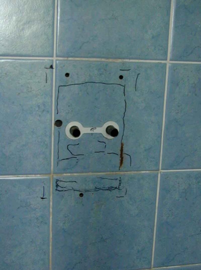
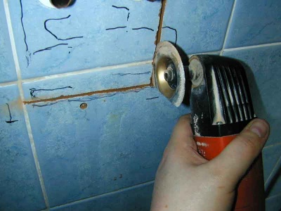
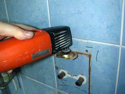
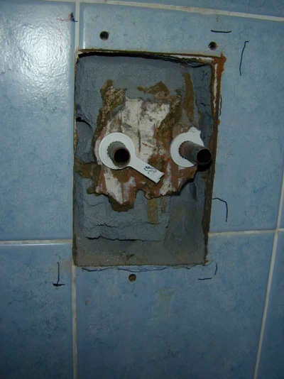
Once the old shower was off, the new faceplate was used to mark out the perimeter. The valve body itself used to work out the size of recess to cut. The first stage is to cut through the tiles without disrupting the bits that are to stay behind. The best tool for this job is an Oscillating tool fitted with a diamond or carbide segment saw.
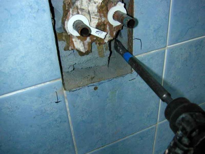
Once the tile is cut all round the perimeter, it can be chipped out with a chisel in a SDS Drill.
When that is done, start sinking the perimeter of the hole deeper into the wall. Create enough space to allow the chisel to be sunk to its final depth without putting too much side force on the existing tiles.
When there is space to chisel to depth freely, mark the final depth required on the chisel, and sink it to this depth all round the edge:
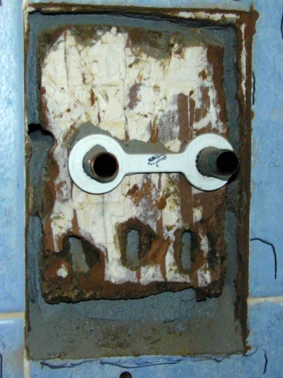
Once the edge is cut to depth, work back from the edge using a wider chisel (e.g. 40mm), to break out the waste material and leave it level at the back:
Cutting side recesses
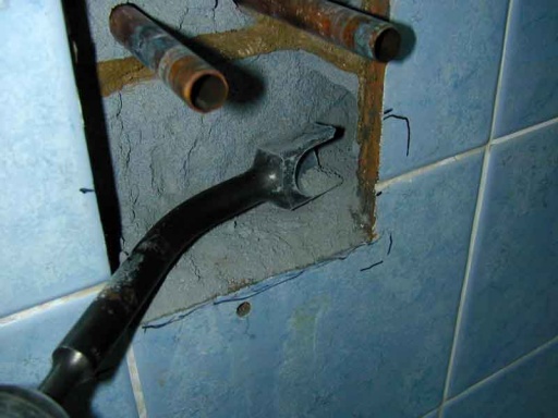
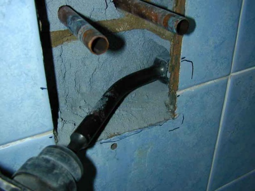
In this case, the valve tails were somewhat wider than the actual faceplate - especially when pipes were connected. This meant it would not be possible to simply cut the required size hole into the wall without also removing tiles that would ultimately still be needed. So it was necessary to cut away wall behind the tiles while leaving them undisturbed. The simplest way to do this is with a cranked gouging chisel:
Carefully extending the recess into the wall, but leaving the tiles and their plaster backing in place.
The same problem existed for the outlet pipe. Like most concealed mixers, the outlet is at the top, so when this is not being plumbed to a fixed "in wall" shower head, this needs routing to one side (so the shower hose does not hang over the controls) for connection to an outlet elbow.
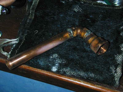
The outlet pipe was soldered up from a female 1/2" BSP socket and a length of pipe on an elbow:
To accommodate the outlet pipe in the wall a 32mm hole was drilled through the tiles to a depth of around 65mm. The recess in the wall was the chassed sideways with the SDS gouge until it met and extended into the hole drilled. Enough material needs to be removed so that the outlet pipe can be inserted and rotated into place.
Pipework
Once complication of this particular install was that the original pipe centres were close together and not ideal for the new valve. They also passed directly through the wall into the adjacent airing cupboard, but access to them on that side was greatly hampered by the presence of the hot water cylinder. So it was decided to deal with the pipe re-routing within the shower valve recess.
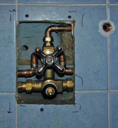
The pipe tails to the shower enter from the sides in a pair of 15mm compression fittings, which in turn screw onto the showers 3/4" BSP unions (with rubber filter washers). To enable a small 180 degree change of direction. a U bend was formed from a 15mm end feed elbow, and a 15mm end feed "street" elbow (i.e. one with male and female ends rather than two female ends).
The outlet pipe was also positioned ready for the valve. (The valve itself can be removed simply by disconnecting the top compression fitting, and undoing the two union nuts).
Fixing and sealing
The outlet pipe connection was sealed to the wall with silicone first, and then the outlet elbow screwed into it (the tail of the elbow needed to be cut to length, and the stub wrapped in PTFE tape to make a good seal on the threads. Winding the PTFE tape thicker nearer to the base of the thread helped create a tightening fit, that keeps the elbow in the correct orientation once it is screwed "home".
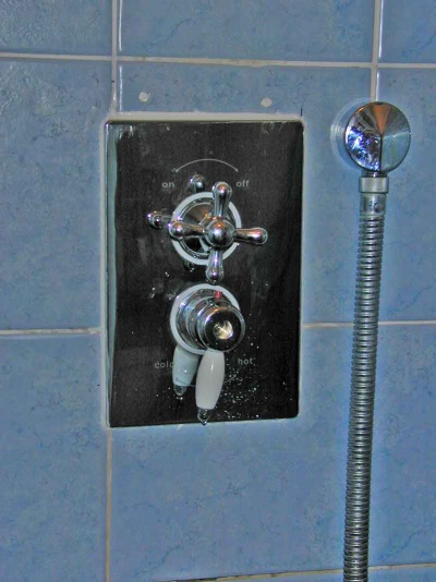
The final finishing plate can now be pushed on, and silicone applied at the top and edges to prevent water tracking behind it from the tiles:
(alas missed two screw holes! filled with silicone for the moment, will see if a more tile looking result can be achieved)
