Difference between revisions of "Make a Sheet Metal Bender"
(image format) |
|||
| Line 20: | Line 20: | ||
==Construction== | ==Construction== | ||
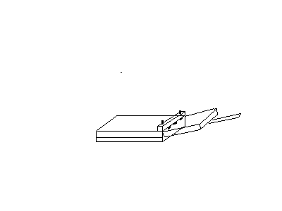
| − | [[Image: | + | [[Image:MetalBender4.gif|Diagram of Metal Bender]] |
The bed, which constitutes the left half of the machine in the diagram, is made from 2 layers of 3/4" wood, each layer at 90 degrees to the other. Thick sheet plywood could be used instead. | The bed, which constitutes the left half of the machine in the diagram, is made from 2 layers of 3/4" wood, each layer at 90 degrees to the other. Thick sheet plywood could be used instead. | ||
Revision as of 04:54, 4 February 2007
This Sheet Metal Bender was made from nothing but scrap wood, 4 hinges, 2 bolts & some screws. Total cost was about £7, and it was made in an afternoon.
The machine successfully bent 19" wide 1.6mm sheet steel. Steel that large and thick was at the limit of what the machine could handle.
Uses
As usual, uses are limited more by imagination than anything else.
- Cases
- Sheet metal furniture
- Car bodywork & some chassis parts
- Shelves with rolled front
- Small steel shelving units
- Brackets
- Trays
- Custom toolboxes
- Square, octagonal, hexagonal etc tabletops with rolled edges
- Trailer panels & parts
Construction
The bed, which constitutes the left half of the machine in the diagram, is made from 2 layers of 3/4" wood, each layer at 90 degrees to the other. Thick sheet plywood could be used instead.
The bending section, on the right, is more of the same with a plank handle attached to make bending easier. The bending section is attached to the bed by 4x heavy duty 4" hinges. Accurate alignment of these hinges is essential. The hinges are all held using 3" wood screws in all holes. Don't use small screws. The handle extends under the full length of the bending section, and is attached with 4 or 5 screws at the hinge end of the handle, and 2 more screws further out.
The top bar, which runs across the top of the machine parallel to the screws, is 3" x 3" timber. It is held to the bed with, at each end, one wingnut & 2 penny washers that screw down onto M8 steel threaded rod.
The 2 holes in the bed for the steel rods are made a tight fit, and the dowel screwed into place. A penny washer and nut on the underside completes the fixing of the threaded bar.
It is possible to use bolts in place of the threaded rod if you have some long enough.
Finally softwood strip feet are added to the base to prevent the threaded rod ends scratching things. The feet must be deep enough for the machine to sit happily with the bending section attached and lying down.
Use
Loosen the wingnuts, and slide your sheet metal under the bar. Do the nuts up tight by hand to hold the sheet metal in place. Don't use a power tool.
Place a binbag on the bending section, between it and the sheet metal, or you can use 2 layers of polythene. The plastic prevents the bending process pushing the workpiece away from the handle.
Stand on the crossbar and lift the bending handle up to bend the metal. If you don't stand on the crossbar, the workpiece will slip during bend.
When bending the maximum width and thickness of steel, it might prove necessary to use clamps to assist the crossbar, or to have a 2nd person also stand on the bar.
Limitations
This is a very basic metal bender, something any DIYer can make easily and at hardly any cost. It is not intended to be high performance equipment, but just to get the job done. It was constructed to fabricate structural car parts, for which it proved quite capable.
The radius of bend is not sharp, due mainly to the limited restraint on the metal.
It is necessary to stand on the cross bar to prevent the metal slipping.
If used regularly with large metal, the bending corner of the bar may become less sharp over time, and the bar need turning and eventual replacement.
Improvements
A much larger section crossbar could eliminate the need to stand on the bar. High forces act on the bar in both directions, so try 4x4 or 5x5 rather than 2x6.
1 or 2 corners of the bar can be rounded to provide bends of larger radius for decorative purposes.
The best improvement is probably to replace the machine entirely with a design that produces a tight bend radius and handles larger steel. Nonetheless this basic design has many uses, and is within the price and time range of any regular DIYer.
Untested
To make U shape sections, maybe a U shaped bar radiused on 2 sides could be used. After the first bend, which creates the lower half of the U, moulding is bolted to the hinged bending section and the upper half of the U is bent. Maybe.
Related
Similar designs are ued to press a C shaped channel into aluminium strips. These are used as heat spreaders in UFH, and as heat collectors in solar panels, with pipe pressed into the channel along the centre. This use requires modification of the design.
