Motorised Valves
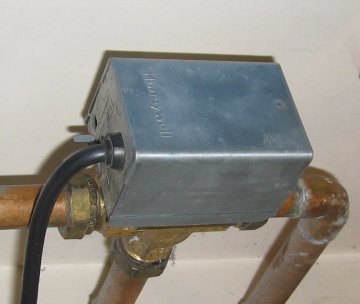
This article is about motorised valves used in central heating systems. Motorised valves are a type of electrically actuated valve (others include solenoid valves and valves using electrically-generated thermal effects).
Motorised valves generally comprise:
- a synchronous electric motor
- gears to reduce the speed and increase the torque output of the motor
The motor and gears are often combined in a package known as a Synchron motor.
- a linkage from the output gear to the hydronic part of the valve
- one or more switches (usually microswitches) actuated by, for example, a cam attached to the output linkage
- a spring: see below
- the above components usually comprise one module, often known as the 'head', which may be detatched from the parts below for repair or replacement.
- a valve controlling flow of water in the hydronic system, actuated by the head: this part is often known as the 'body'.
Configurations of motorised valve
Valves are commonly found in the following configurations:
2-port
The valve has 2 pipe connections (ports) and permits or blocks flow between the ports depending on whether it is actuated or not. Flow is permitted when the valve is actuated and blocked in its resting state.
When the valve is energised a synchronous motor drives the valve to the open position until the motor stalls and stays in that position. When the valve is required to close then power is removed and a spring pulls the mechanism (and the motor) back, returning it to its original, closed, position.
3-port
The valve has 3 pipe connections, in a T formation. The centre leg of the T is the inlet and the two short arms are the outlets, usually referred to as ports A and B. Actuation controls whether the flow from the inlet passes to the A or B port. In the resting state flow is to the B port (usually the hot water circuit).
There are two types of 3-port valve:
- Diverter valve
- This is a simple change-over version of a 3-port valve: when the valve is actuated all flow is diverted from one port to the other. When deactivated, a spring returns flow back to the original port - there is no mid position that can feed water to both ports at once.
- Mid-position valve
- In this type of valve there is a stable state in which flow from the inlet can pass to both (A and B) outlet ports simultaneously. This type of valve is commonly found in domestic central heating systems where it controls flow of hot water from a boiler to hot water and radiator circuits in a Y-plan system configuration.
It should also be noted that these mid position valves usually contain a lever underneath the motor head. This can be used to move the valve physically to the mid position for flushing the system. This is used when refilling the system and bleeding all the air out of the system. After use it must be returned to the default rest position as driven by the spring (B HW demand)
These 3 port valves were originally pioneered by Honeywell to support their Y Plan. A particularly annoying feature is that the valve had no physical valve position indicator (as per the Switchmaster below). This was a time waster for a technician faced with a faulty CH system and possible sticky valve. Even the modern Sunvic MoMO valve only has a rudimentary mid position indicator which can be difficult or impossible to observe. An experiment has shown that a coloured disc can be fitted around the valve shaft once the motor head has been removed - easy job not invalidating the guarantee. It is also advisable when installing a system, to provide gate valves on all 3 connections to make changeout easy without the need for a complete time wasting drain down.
There is a detailed explanation of the workings of these valves here.
Types of motorised valve
Spring return valves
In these types when power is applied the motor and gears act against the force of a spring to operate the valve. When power is removed the spring returns the valve to its resting position. In a 2-port valve this is the closed position. In a 3-port valve the resting position is where flow from the inlet passes to the B port (DHW).
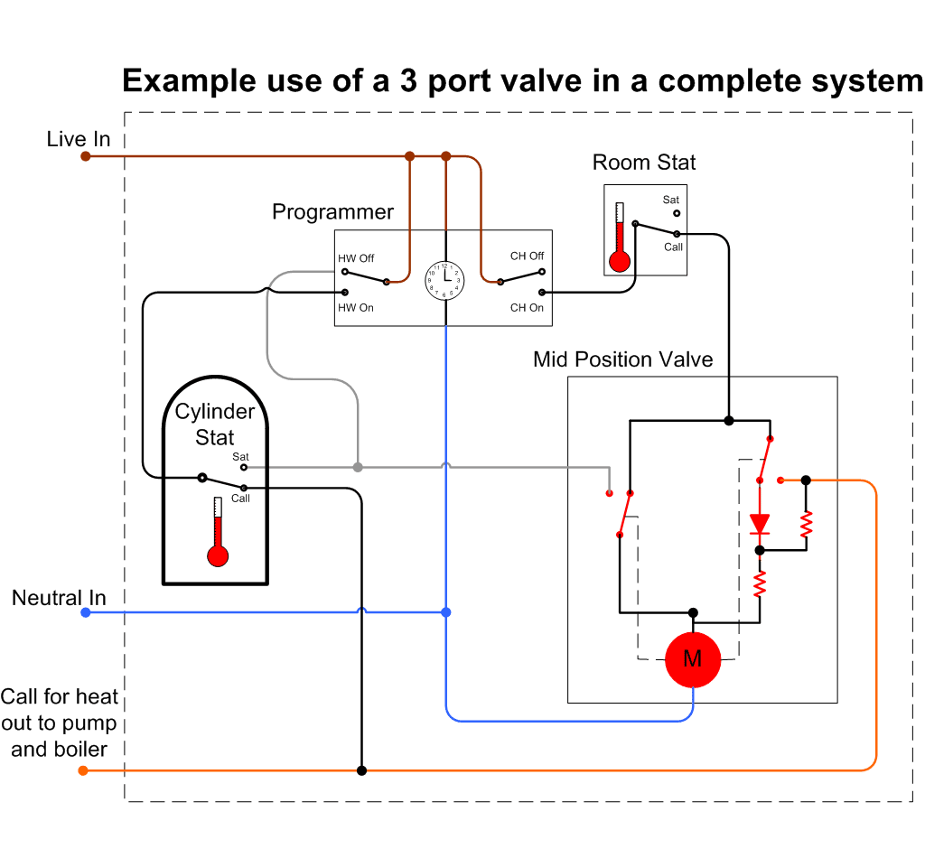
These types of valve consume power whenever they active - typically when the system controls are calling for heat. In in the case of the mid position 3-port valve, they may also still consume power when all the calls for heat are satisfied (see suggested modification below to "fix" this. In 2-port valves the motor runs until the valve is fully open and then stalls as the actuator mechanism cannot move any further. 3-port valves are more complicated: a description can be found here. An example of how a 3-port valve integrates into a system:
For detailed wiring diagrams of Y Plan and other zoning systems see the main CH Zoning article.
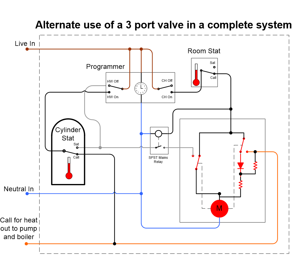
Alternate Y plan circuit
Wiki reader Anthony Ford, contributed the following design modification which circumvents the situation where a valve can remain powered for an extended period even when all the calls for heat are satisfied. The modification introduces an additional relay into the control wiring to allow the valve to spring return completely when all calls for heat are satisfied.
The relay used can be either a traditional coil based SPST device, or a modern solid state device, so long as the input is rated for operation at mains voltage, and the relay can switch an inductive load of a few amps. See the Using relay controls section of this article for more information on providing noise and transient suppression when using relays in mains electrical systems.
Alternate Y plan circuit, with indicators
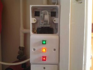
Wiki reader Anthony Ford in addition to the above also submitted the following design modification to provide position indication
One of the criticisms of the traditional three port valve is that it does not include any form of indicator to show either its position or what heating demands are actually active at any given time. This makes diagnosing and troubleshooting problems with the heating system harder than they need be. The following variation of the above circuit not only includes the ability to turn the valve completely "off" when all demands are satisfied, but also allows the addition of indicator lamps to show what the heating demands actually are.The DPDT relay with the NO/NC contacts positioned in the wires as shown is necessary to prevent back feeds giving false indication. eg. If the hot water is satisfied but the central heating calling the orange wire from the valve would be live. In this state without the relay contact the CH calling light would be illuminated and also false indication that the HW is also calling.a similar situation exists with the HW satisfied indication.
Description of operation The
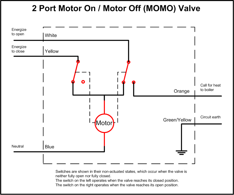
Motor On / Motor Off (MOMO) valves
In these types of valve the motor is used to drive the motor from one position to the next. Switches in the mechanism stop the motor when it has reached its desired position.
Since the motor only runs whilst the valve is changing from one state to another there is a saving in energy compared to valves where the motor runs continuously while the valve is open. Such valves may also be more reliable since the motor and surrounding components will run cooler.
2-port
This type of valve changes from it closed (off) to its open (on) position when power is applied to one terminal, and from open to closed when power is applied to another terminal.
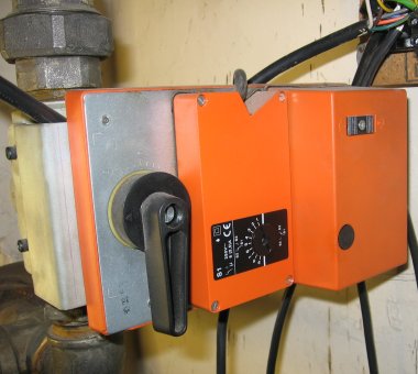
These types of valves are occasionally found in domestic central heating systems: usually as Satchwell or Sunvic valves with grey plastic heads. Sunvic manufacture both MOMO and spring-return valves in similar casings.
If a motor-open/motor-close valve is replaced by a spring-return valve, or vice-versa, the controls wiring must be modified to suit. In the case of replacing a spring-return with a MOMO valve this requires change-over contacts at the room thermostat (or progstat) and an extra wiring conductor between the 'stat and the valve.
| This type of valve is also found in non-domestic installations. |
3-port
Sunvic's SDMV series 3-port valves are motor-on/motor-off (MOMO) types but are wired identically to spring-return valves. Since they only consume power when moving from one position to another (A to mid-position, mid-position to B, B to mid-position and mid-position to A) they save electrical power compared to spring-return 3-port valves. Compared to the Honeywell-type 3-port valve's 2 microswitches, one diode and 2 resistors the Sunvic valves contain more electronics: two relays and 3 micro-switches. Additionally they use two circuits each comprising a mains-voltage capacitor, bridge rectifier, electrolytic capacitor and diode to drive the relays which are 24V DC coil types, rather than using relays with mains-voltage coils: presumably the latter would be larger and/or more expensive than components of these circuits. However despite the (still relatively modest) amount of electronics in the Sunvic valves they may be expected to be more reliable than the spring return valves since:
- the motor does not have to overcome the pull of the spring when moving towards the B position, and uses the motor rather than a spring to return all the way back to the A position, so a motor of given power can deal with greater friction in the mechanical components of the valve before failing to operate it properly
- the valve head runs cooler as it is not dissipating heat from the electrical current passing for hours on end, which should reduce heat-related failure of components
Switchmaster
Switchmaster valves with bright blue plastic heads are found in some older domestic installations.
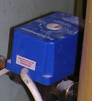
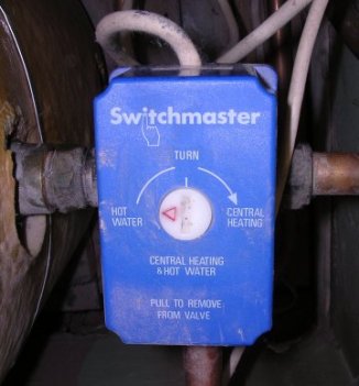
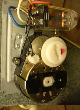
- A thread on uk.d-i-y suggests that these are NOT wired as for spring-return - cf Y Plan schematic diagram above).
| red | sw live to boiler & pump |
| orange | HW on (from cylinder 'stat) |
| white | HW off (from cylinder stat) |
| yellow | CH on (from room 'stat) |
| blue | neutral |
| green/yellow | earth |
- Another thread discusses wiring and plumbing changes required to replace this type of valve.
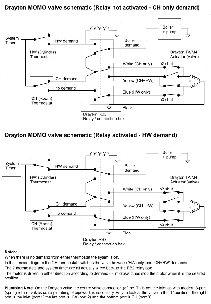
This MOMO valve from the 1970/80s has largely disappeared. The actuator used just 4 wires: a neutral and 3 others (only one of which was live at any instant) which drove the valve to each of the 3 positions. The design has the following features:
- Valve positioning is done via a single relay in the wiring box and 4 microswitches in the actuator.
- The low gearing means that the motor can still move the valve as it stiffens up with age (although it takes 2 and half minutes to move from end to end).
- The motor gearing is all metal.
- There is a valve position indicator which is also a manual override (allowing the valve to be put at any position quickly by hand). The valve re-engages with the actuator when they next align.
- The weak spot was the large single piece plastic cam used between the motor and the valve. Eventually the metal parts started to grind away the plastic at one end or the other and spares were no longer available (although this author has rebuilt both ends of his cam with metal parts and it has been running now since 1978).
- The usual MOMO advantages of only drawing power when changing position and being positively driven in both directions.
- The wiring is not compatible with modern spring return 3-port valves; the Flow-share requires CH CALL and SAT and only HW CALL whereas spring-return types require only CH CALL but HW CALL and SAT.
- The pipework arrangement is also different from modern valves, with inlet being on one of the short arms of the 'T' and the central leg of the 'T' being the CH out port.
