Difference between revisions of "Split-type Room Air Conditioner"
(Added the need for the electrical power supply to deliver the rated current for the system) |
m (Added to new cat) |
||
| (22 intermediate revisions by 2 users not shown) | |||
| Line 2: | Line 2: | ||
== Foreword == | == Foreword == | ||
| − | The split-type room air conditioner has two parts, an indoor unit and an outdoor unit, | + | The split-type room air conditioner has two parts, an indoor unit and an outdoor unit, connected together by a refrigerant flowing through a pair of pipes. The design puts the bulk of the equipment out of doors, leaving a reasonably stylish unit to hang on the wall in the room. Systems are available from various suppliers. It is impossible to provide meaningful illustrations without identifying my own particular system, but nothing I write here is intended to be an endorsement or indeed a criticism of this particular product. |
I completed this project on 29 July 2017, and to the best of my knowledge and belief the work complies with the applicable parts of National planning regulations, local building control, and the wiring regulations and practices in use at the time. I also discussed and agreed the project with my neighbours, which seems to me (in England at least) the decent and proper thing to do. | I completed this project on 29 July 2017, and to the best of my knowledge and belief the work complies with the applicable parts of National planning regulations, local building control, and the wiring regulations and practices in use at the time. I also discussed and agreed the project with my neighbours, which seems to me (in England at least) the decent and proper thing to do. | ||
| Line 10: | Line 10: | ||
=== General === | === General === | ||
| − | The essential precautions before starting (and indeed, before buying | + | The essential precautions before starting (and indeed, before buying a system) are to make sure you can secure the indoor and outdoor units onto something sufficiently solid to hold their weight, and you can make a 65 to 75 mm diameter hole through the wall to take three pipes and a electric cable. These services can run along the surface of the wall indoors (perhaps in trunking) but a hole behind the indoor unit makes for a neater job. This implies, the indoor unit must go on an outside wall. When you bend the pipes, the smallest radius you can hope to achieve is about 100 mm, with 120 mm or so being a lot easier. |
=== Building Regulations === | === Building Regulations === | ||
| − | [[image:ac_efficiency_label_without_manufacturer.jpg|thumb| | + | [[image:ac_efficiency_label_without_manufacturer.jpg|thumb|The energy efficiency label includes the suitability of the system for heating in the geographical location (the green shading includes the East of England)]] |
The building regulations in England are complex. Looking at the Domestic Building Services Compliance Guide published by HM Government in 2013 and effective from 6 April 2014 for use in England, the regulations make recommendations for domestic air conditioning systems but do not appear to enforce rules beyond the existing standards for the electricity supply and structural stability and so on. | The building regulations in England are complex. Looking at the Domestic Building Services Compliance Guide published by HM Government in 2013 and effective from 6 April 2014 for use in England, the regulations make recommendations for domestic air conditioning systems but do not appear to enforce rules beyond the existing standards for the electricity supply and structural stability and so on. | ||
| Line 20: | Line 20: | ||
Section 10 of the Compliance Guide gives a recommended minimum energy efficiency ratio (EER) of 2.4 for air conditioners working in cooling mode, while the specification of my system claims a EER (in BTU/hr.W) of SEER 6.1. | Section 10 of the Compliance Guide gives a recommended minimum energy efficiency ratio (EER) of 2.4 for air conditioners working in cooling mode, while the specification of my system claims a EER (in BTU/hr.W) of SEER 6.1. | ||
| − | There are also recommendations for the work to be carried out by an installer recommended by the supplier (being, for this system a DIY person), for competence and for the person to hold a valid refrigeration certificate. The installation of my system involves the release of refrigerant from the outdoor unit (pre-charged) into the rest of the system, but not the procurement or handling of refrigerant in bottles. | + | There are also recommendations for the work to be carried out by an installer recommended by the supplier (being, for this system, a DIY person), for competence and for the person to hold a valid refrigeration certificate. The installation of my system involves the release of refrigerant from the outdoor unit (pre-charged) into the rest of the system, but not the procurement or handling of refrigerant in bottles. |
The refrigeration pipes should be insulated and protected against accidental damage. | The refrigeration pipes should be insulated and protected against accidental damage. | ||
| Line 36: | Line 36: | ||
* The installation does not result in the presence of more than one air source heat pump on the same building or within the curtilage of the building | * The installation does not result in the presence of more than one air source heat pump on the same building or within the curtilage of the building | ||
| − | * The volume of the outdoor unit is less than 0.6 cubic metres | + | * The volume of the outdoor unit is less than 0.6 cubic metres (this would be quite enormous) |
* The outdoor unit is more than one metre from the boundary (actually, about 1.5 metres) | * The outdoor unit is more than one metre from the boundary (actually, about 1.5 metres) | ||
* The outdoor unit is not installed on a roof (it is on the ground) | * The outdoor unit is not installed on a roof (it is on the ground) | ||
| − | Class G also has a curious condition: "''the air source heat pump shall be used solely for heating purposes''". I do not know what this means, but perhaps "heating purposes", means changing the temperature inside a building | + | Class G also has a curious condition: "''the air source heat pump shall be used solely for heating purposes''". I do not know what this means, but perhaps "heating purposes", means changing the temperature inside a building rather than exporting heat through pipes to the neighbourhood. I cannot believe the heat pump is allowed to run one way but not the other. |
=== Neighbours === | === Neighbours === | ||
| Line 48: | Line 48: | ||
=== Electrical Power Supply === | === Electrical Power Supply === | ||
| − | The small systems like mine come with a fitted 13 amp plug and run happily from a socket on the ring - the | + | The small systems like mine come with a fitted 13 amp plug and run happily from a socket on the ring - the nominal load on the electrical supply is given as 800 watts (but see below). Larger systems need a dedicated radial circuit from the consumer unit. |
| − | A reversible system like this will typically have three specifications for its electrical current consumption: cooling current, heating current and rated current. The cooling current and the heating current relate to the | + | A reversible system like this will typically have three specifications for its electrical current consumption: cooling current, heating current and rated current. The cooling current and the heating current relate to the metered electrical energy the system uses during its normal operation, while the rated current defines minimum requirements for the capacity of the electrical supply. An air conditioner uses electric motors and so it draws its maximum current when it starts - for my system, the cooling current and the heating current are about 3.4 A (about 800 W), but the rated current is 9.0 A (a momentary load of nearer to 2 kW). |
| − | The use of a 13 amp plug follows the approach taken for my gas-fired central heating boiler, and gives a straightforward way to isolate the system for maintenance. This approach is not ideal because the air conditioner is designed to be shut down in an orderly way, initiated by pressing a button on | + | The use of a 13 amp plug follows the approach taken for my gas-fired central heating boiler, and gives a straightforward way to isolate the system for maintenance. This approach is not ideal because the air conditioner is designed to be shut down in an orderly way, initiated by pressing a button on a remote control. Also I can imagine that pulling out the plug when the motors are running might present a voltage from the back emf across the live and neutral pins on the plug, and I do not know whether the system includes safeguards to reduce such a voltage to a safe level. I would follow this up if I had a toddler in the home, but the obvious alternative is to use a switched fused connection unit, which avoids such a scenario. |
At the moment, the system does not have a permanent earth connection. The enclosure of the indoor unit is wholly plastic (and its steel mounting bracket is inaccessible), but the outdoor unit has a steel enclosure. Clearly, the use of a 13A plug gives an earth connection detachable without the use of a tool, and the scenario here is not comparable to my illustration of a central heating boiler attached to pipes which are themselves bonded to earth. Removing the plug takes the supply of electricity away from the system, but any electricity stored inside (for example in motor capacitors) might remain for some time. | At the moment, the system does not have a permanent earth connection. The enclosure of the indoor unit is wholly plastic (and its steel mounting bracket is inaccessible), but the outdoor unit has a steel enclosure. Clearly, the use of a 13A plug gives an earth connection detachable without the use of a tool, and the scenario here is not comparable to my illustration of a central heating boiler attached to pipes which are themselves bonded to earth. Removing the plug takes the supply of electricity away from the system, but any electricity stored inside (for example in motor capacitors) might remain for some time. | ||
| − | |||
| − | |||
=== Specifying the System === | === Specifying the System === | ||
| − | My system is one of the smallest of its kind currently on the market (Summer 2017) – it is | + | My system is one of the smallest of its kind currently on the market (Summer 2017) – it is claimed to move heat at a rate of about 2.5 kW (9,000 BTU per hour), enough for a room twice the size of mine. This is not necessarily a good thing – an over-specified system can cool the room too quickly, before it has had time to take the moisture out of the air, and this makes for an environment less comfortable than it really should be. Conversely, a slightly under-specified system will merely struggle to keep up on a really hot day, and in the East of England this will rarely be a great problem. In my case, the room is an outbuilding where the door opens directly into my garden, and the additional capacity will help the system to cope with the door being left open from time to time. |
== The DIY Air Conditioner Kit == | == The DIY Air Conditioner Kit == | ||
| Line 80: | Line 78: | ||
Opening both boxes indoors reveals something of a “new car smell” which seems to emanate from the indoor unit. This unit arrives pressurised with air as a factory precaution to show it is gas-tight when it arrives. Perhaps a tiny bit of Chinese air has made its way out during the trip across to England. The outdoor unit is also pressurised, but with the refrigerant which will flow around the completed system. | Opening both boxes indoors reveals something of a “new car smell” which seems to emanate from the indoor unit. This unit arrives pressurised with air as a factory precaution to show it is gas-tight when it arrives. Perhaps a tiny bit of Chinese air has made its way out during the trip across to England. The outdoor unit is also pressurised, but with the refrigerant which will flow around the completed system. | ||
| − | Looking at the parts supplied, everything is minimal and easy to comprehend. The indoor unit comes with two short copper pipes for the refrigerant (vapour and liquid), the condensate drain pipe, and two long electric cables already attached. The flap underneath the unit is motor-driven and if you try to open it by hand it may never quite close again neatly after operation. | + | Looking at the parts supplied, everything is minimal and easy to comprehend. The indoor unit comes with two short copper pipes for the refrigerant (vapour and liquid), the condensate drain pipe, and two long electric cables, all already attached. The flap underneath the unit is motor-driven and if you try to open it by hand it may never quite close again neatly after operation. Inside the same box there is also a metal wall bracket, a plastic cylinder to line the hole through the wall, some insulating foam and a remote control unit. There are three instruction books – one for installation and maintenance, one for operation, and one for the App. This last one being a sign of the times I guess. |
The outdoor unit is in the second box, along with the two lengths of copper pipe to join the two units together. | The outdoor unit is in the second box, along with the two lengths of copper pipe to join the two units together. | ||
| Line 92: | Line 90: | ||
Fundamentally, this system is a heat pump which uses two small-bore copper pipes to move heat from one place to another. The pipes carry a refrigerant (R410A) – a larger pipe for vapour and a smaller pipe for liquid. | Fundamentally, this system is a heat pump which uses two small-bore copper pipes to move heat from one place to another. The pipes carry a refrigerant (R410A) – a larger pipe for vapour and a smaller pipe for liquid. | ||
| − | I show the indoor unit higher than the outdoor unit because this is how they are arranged in my installation, but the outdoor unit can go higher than the indoor unit instead | + | I show the indoor unit higher than the outdoor unit because this is how they are arranged in my installation, but the outdoor unit can go higher than the indoor unit instead. |
| − | The T-branch valve on the outdoor unit provides access for purging air from the system during setting up, and for future maintenance on the refrigerant circuit. | + | Apart from the indoor and outdoor units, there are the two copper pipes (orange), a plastic pipe (dotted) and two electric cables (blue) to be installed. The T-branch valve on the outdoor unit provides access for purging air from the system during setting up, and for future maintenance on the refrigerant circuit. |
== Outdoor Unit == | == Outdoor Unit == | ||
| Line 106: | Line 104: | ||
Bearing in mind this is England, it seems sensible to raise the outdoor unit high enough to avoid the worst of the annual leaf fall and indeed the occasional flurry of snow. It would be pretty galling to return home from a trip away to find the unit shut down by a blockage. So I am putting the outdoor unit on a pair of timber beams, a bit like skis. | Bearing in mind this is England, it seems sensible to raise the outdoor unit high enough to avoid the worst of the annual leaf fall and indeed the occasional flurry of snow. It would be pretty galling to return home from a trip away to find the unit shut down by a blockage. So I am putting the outdoor unit on a pair of timber beams, a bit like skis. | ||
| − | The beams are from a 150 x 75 mm softwood fence post, 1.8 metres long and cut in half with a hand saw. This sort of task is easier to do than spend time thinking about – the cutting took less than ten minutes. The beams spread the weight as well as providing the lift above ground level, and avoid a heavy construction in bricks or concrete. | + | The beams are from a 150 x 75 mm softwood fence post, 1.8 metres long and cut in half with a hand saw. This sort of task is easier to do than spend time thinking about – the cutting took me less than ten minutes. The beams spread the weight as well as providing the lift above ground level, and avoid a heavy construction in bricks or concrete. |
The four mounting feet of the outdoor unit rather scrunched down when I tightened the coach screws. A perfectionist, which means me, would try to insert some thick washers under the feet if doing this again. The paint pretty much falls off the metal when it sees a spanner, so a little care tightening the screws will help to preserve the original finish. | The four mounting feet of the outdoor unit rather scrunched down when I tightened the coach screws. A perfectionist, which means me, would try to insert some thick washers under the feet if doing this again. The paint pretty much falls off the metal when it sees a spanner, so a little care tightening the screws will help to preserve the original finish. | ||
| Line 112: | Line 110: | ||
The beams ended up parallel with each other but with one end about 6 mm higher than the other, just enough to annoy me, and I used some pieces of slate to pack one end of them up to be level. | The beams ended up parallel with each other but with one end about 6 mm higher than the other, just enough to annoy me, and I used some pieces of slate to pack one end of them up to be level. | ||
| − | I have added a couple of metal straps to stop the unit taking a walk under its own vibration, or indeed if I trip over it when I walk past in the dark. This location is supposed to be the “service area” of my garden, and it is not a frequent walking route, but I do keep | + | I have added a couple of metal straps to stop the unit taking a walk under its own vibration, or indeed if I trip over it when I walk past in the dark. This location is supposed to be the “service area” of my garden, and it is not a frequent walking route, but I do keep my water butt here. I “made” the straps by buying the longest metal strap I could find in the local DIY shop and cutting and bending it to suit. Incidentally I bought the coach screws at the local agricultural wholesaler. They charge pennies per item, and you can buy the exact quantity you need. |
== Indoor Unit == | == Indoor Unit == | ||
| Line 120: | Line 118: | ||
=== Installation Location === | === Installation Location === | ||
| − | The location for the installation of the indoor unit was easy to find. The unit should be 2 metres above the floor, to provide for the most efficient operation, and must be 150 mm below the ceiling, to allow for sufficient air flow. With a floor-to-ceiling height of 2.07 metres at this location (the lowest point under a sloping ceiling), I ended up with the unit a little closer to the floor than the ideal. This technically reduces the effective capacity of the system, but not by enough to have a tangible effect. The efficiency of the system reduces with poor room insulation and a lower location for the indoor unit, and the whole system will be de-rated by most of 50% if the unit is placed | + | The location for the installation of the indoor unit was easy to find. The unit should be 2 metres above the floor, to provide for the most efficient operation, and must be 150 mm below the ceiling, to allow for sufficient air flow. With a floor-to-ceiling height of 2.07 metres at this location (the lowest point under a sloping ceiling), I ended up with the unit a little closer to the floor than the ideal. This technically reduces the effective capacity of the system, but not by enough to have a tangible effect. The efficiency of the system reduces with poor room insulation and a lower location for the indoor unit, and the whole system will be de-rated by most of 50% if the unit is placed on a dwarf wall in a conservatory. |
=== Pressurisation Check === | === Pressurisation Check === | ||
| Line 129: | Line 127: | ||
[[image:ac_indoor_unit_pipe_spring.jpg|thumb|Pipes with integral bending spring]] | [[image:ac_indoor_unit_pipe_spring.jpg|thumb|Pipes with integral bending spring]] | ||
| − | [[image:ac_indoor_unit_pipe_locations.jpg|thumb|Pipes manipulated to final locations]] | + | [[image:ac_indoor_unit_pipe_locations.jpg|thumb|Pipes manipulated to final locations ... the unit is resting on the upholstered arms of a chair to protect the finish of the glossy front panel]] |
You can have the pipes (and the cables) exiting from the left, the rear or the right-hand sides of the unit, with the pipes as delivered aligned to the left. The installation manual has good advice on how to bend the pipes around for access to the rear (or the right-hand end), and this is straightforward if a little unnerving for a beginner to do. The larger pipe (which is rather more difficult to bend) has a spring to support it during adjustments. | You can have the pipes (and the cables) exiting from the left, the rear or the right-hand sides of the unit, with the pipes as delivered aligned to the left. The installation manual has good advice on how to bend the pipes around for access to the rear (or the right-hand end), and this is straightforward if a little unnerving for a beginner to do. The larger pipe (which is rather more difficult to bend) has a spring to support it during adjustments. | ||
| Line 135: | Line 133: | ||
After several minutes of gentle manipulation the arrangement of the pipes looks like this. The black insulation is a split sleeve around the two gas pipes, and the white pipe is the drain pipe. The black cable is the control cable, and the white cable is the mains supply. You can see where I have removed the knock-out slot for the mains supply cable, and also the much larger moulded knock-out available for use if the pipes are leaving the unit at the end. | After several minutes of gentle manipulation the arrangement of the pipes looks like this. The black insulation is a split sleeve around the two gas pipes, and the white pipe is the drain pipe. The black cable is the control cable, and the white cable is the mains supply. You can see where I have removed the knock-out slot for the mains supply cable, and also the much larger moulded knock-out available for use if the pipes are leaving the unit at the end. | ||
| − | The natural movement is to rotate each pipe around its existing bend, and this activity left me with my pipes exiting about 15 mm lower down the unit than I really wanted them. Fairly clearly, although you can put a tight bend where you want it on a virgin length of straight pipe, it is all but impossible to move | + | The natural movement is to rotate each pipe around its existing bend, and this activity left me with my pipes exiting about 15 mm lower down the unit than I really wanted them. Fairly clearly, although you can put a tight bend where you want it on a virgin length of straight pipe, it is all but impossible to move an existing bend 15 mm along a pipe. |
=== Hole through Wall === | === Hole through Wall === | ||
| Line 160: | Line 158: | ||
The wall bracket is made from a pressing of relatively thin sheet steel. The bracket is strong enough to hold the 10 kg of indoor unit, but the two lugs for hanging the unit moved outwards while I manoeuvred the unit into place. So my indoor unit is hanging about two millimetres away from the wall at the top. I also cut a rebate out of the bottom of the enclosure of indoor unit, to let the unit touch the wall at the bottom. | The wall bracket is made from a pressing of relatively thin sheet steel. The bracket is strong enough to hold the 10 kg of indoor unit, but the two lugs for hanging the unit moved outwards while I manoeuvred the unit into place. So my indoor unit is hanging about two millimetres away from the wall at the top. I also cut a rebate out of the bottom of the enclosure of indoor unit, to let the unit touch the wall at the bottom. | ||
| − | If I had a second pair of hands I would look at putting some shims into the lugs on the wall bracket, but the indoor unit is quite an unwieldy thing above your head (especially with no headroom!) and with it sitting on its bracket I decided it was best to leave it there. Bearing in mind the unit is for installation close to a ceiling, I do wonder if a pair of simple screw lugs with keyhole slots (like glass plates) would make for an easier design. Anyway, with this done the difficult part of the job was over. | + | If I had a second pair of hands I would look at putting some shims into the lugs on the wall bracket, but the indoor unit is quite an unwieldy thing above your head (especially with no headroom!) and with it sitting on its bracket I decided it was best to leave it there. Bearing in mind the unit is for installation close to a ceiling, I do wonder if a pair of simple screw lugs with keyhole slots (like glass plates) would make for an easier design. Anyway, with this done the only difficult part of the job was over. |
<br clear=all> | <br clear=all> | ||
| Line 171: | Line 169: | ||
[[image:ac_pipes_valves.jpg|thumb|Pipes connected to outdoor unit]] | [[image:ac_pipes_valves.jpg|thumb|Pipes connected to outdoor unit]] | ||
| − | + | The next task is to form the copper pipes poking out through the wall into shapes to meet the long pipes linking to the outdoor unit. The pipes are easy enough to bend as long as you take your time. The technique is to apply an even pressure with all fingers and both thumbs, then move along 15 mm or so and repeat, and so on. The larger pipe is more difficult to bend, so it is sensible to form this one first to the best shape you can, and then bend the smaller pipe to match. | |
The plastic pipe covers are still in place here to keep the pipe connections as scrupulously clean as I can manage. The machined conical connections are behind them, with the pipe flares on the long pipes to connect to them. The black foam insulation is pulled away to let me manipulate the pipes into place and is tied into place later. The white pipe is the drain pipe, located at the bottom of the bundle to make sure it drains correctly, and the black cable is the control cable. | The plastic pipe covers are still in place here to keep the pipe connections as scrupulously clean as I can manage. The machined conical connections are behind them, with the pipe flares on the long pipes to connect to them. The black foam insulation is pulled away to let me manipulate the pipes into place and is tied into place later. The white pipe is the drain pipe, located at the bottom of the bundle to make sure it drains correctly, and the black cable is the control cable. | ||
| Line 183: | Line 181: | ||
A fresh correspondence with the supplier confirmed that it is fine to run the pipes both downwards and upwards between the indoor and outdoor units. This lets me take the easiest route for them – down the wall behind the building, through the void under the floor, and then up again and finally down to reach the valves on the outdoor unit. I began with the thicker pipe again, first creating the straight run to drop down the wall, and then forming a curve to take the pipe around and into the floor void. With the first half of this pipe in place I made off its connection to the short pipe from the indoor unit, and then formed new bends and made off its connection to the outdoor unit. | A fresh correspondence with the supplier confirmed that it is fine to run the pipes both downwards and upwards between the indoor and outdoor units. This lets me take the easiest route for them – down the wall behind the building, through the void under the floor, and then up again and finally down to reach the valves on the outdoor unit. I began with the thicker pipe again, first creating the straight run to drop down the wall, and then forming a curve to take the pipe around and into the floor void. With the first half of this pipe in place I made off its connection to the short pipe from the indoor unit, and then formed new bends and made off its connection to the outdoor unit. | ||
| − | When you remove the first plastic cap from a pipe on the indoor unit, you lose the last of its factory pressurisation, and it seems sensible to assemble the joint promptly to avoid the ingress of any dust or dirt. I do not possess many large spanners but by chance I found both 17 and 22 mm open-ended ones, and these let me tighten the pipe fittings with the confidence you get with a conventional spanner. The fittings are lightly oiled before assembly, and then assembled to make a gas-tight seal. Effectively you are crushing and deforming a copper flange (the flare) against a conical surface to make each joint, so clearly the joints really do need to be very tight indeed. The installation manual suggests, “as tight as a car wheel nut”, and I suggest, possibly a little tighter. The last thing you want during this activity is for a spanner to slip and you to take the skin off your knuckles, so I suggest a couple of decent spanners are better than adjustable ones. | + | When you remove the first plastic cap from a pipe on the indoor unit, you lose the last of its factory pressurisation, and it seems sensible to then assemble the joint promptly to avoid the ingress of any dust or dirt. I do not possess many large spanners but by chance I found both 17 and 22 mm open-ended ones, and these let me tighten the pipe fittings with the confidence you get with a conventional spanner. The fittings are lightly oiled before assembly, and then assembled to make a gas-tight seal. Effectively you are crushing and deforming a copper flange (the flare) against a conical surface to make each joint, so clearly the joints really do need to be very tight indeed. The installation manual suggests, “as tight as a car wheel nut”, and I suggest, possibly a little tighter. The last thing you want during this activity is for a spanner to slip and you to take the skin off your knuckles, so I suggest a couple of decent spanners are better than adjustable ones. Ordinary spanners are also likely to be longer than adjustable ones, which helps you to feel the tightness as you go along. |
| − | The smaller pipe is easier to run in, and just as hard to connect, but the result looks nice to me. Looking at the ends at the outdoor unit, the grey insulating sleeving here is supplied as one piece in the kit, but it makes for a neater job to cut it and apply two short lengths. | + | The smaller pipe is easier to run in, and just as hard to connect, but the result looks nice to me. Looking at the ends of the pipes at the outdoor unit, the grey insulating sleeving here is supplied as one piece in the kit, but it makes for a neater job to cut it and apply two short lengths. |
<br clear=all> | <br clear=all> | ||
| Line 197: | Line 195: | ||
[[image:ac_outdoor_unit_complete.jpg|thumb|End cover on outdoor unit]] | [[image:ac_outdoor_unit_complete.jpg|thumb|End cover on outdoor unit]] | ||
| − | With the pipes and the wiring all assembled, the time comes to set up the system. Essentially, you use a small shot of the refrigerant from the outdoor unit to pressurise the system. Check for leaks at every joint using soapy water. Then expel the air from the system, and check for leaks again. And finally fill the system with all of the remaining refrigerant, and do a third check for leaks. I had one leak, which I found on the first round, and nipping up the joint with the spanner sorted it out. This was the smaller pipe at the outdoor unit. When the joint | + | With the pipes and the wiring all assembled, the time comes to set up the system. Essentially, you use a small shot of the refrigerant from the outdoor unit to pressurise the system. Check for leaks at every joint using soapy water. Then expel the air from the system, and check for leaks again. And finally fill the system with all of the remaining refrigerant, and do a third check for leaks. I had one leak, which I found on the first round, and nipping up the joint with the spanner sorted it out. This was the smaller pipe at the outdoor unit. When I tightened the joint, I watched the enclosure of the unit bow out and then relax itself. |
And so, with the control cable and the pipes connected up, it is time to try everything out. The indoor unit plugs into a 13A socket and, when you press the power button on the remote control, the display obligingly lights up and the machine opens its air flap. Seeing everything start up and run for a couple of minutes, I shut it down and tidied up the installation with foam insulation around the ends of the copper pipes and putting the access cover back onto the outdoor unit. | And so, with the control cable and the pipes connected up, it is time to try everything out. The indoor unit plugs into a 13A socket and, when you press the power button on the remote control, the display obligingly lights up and the machine opens its air flap. Seeing everything start up and run for a couple of minutes, I shut it down and tidied up the installation with foam insulation around the ends of the copper pipes and putting the access cover back onto the outdoor unit. | ||
| − | Then I restarted the system and ran it flat out as instructed in the installation manual - maximum chill for 35 minutes, and then maximum heat for as long again. The “new car smell” returned to the room for an hour or so, then faded away. The initial impression of performance exceeds my expectations. With the ambient temperature outdoors sitting around 23 | + | Then I restarted the system and ran it flat out as instructed in the installation manual - maximum chill for 35 minutes, and then maximum heat for as long again. The “new car smell” returned to the room for an hour or so, and then faded away. The initial impression of performance exceeds my expectations. With the ambient temperature outdoors sitting around 23 to 24C, this activity took the temperature at the far side of the room (opposite the indoor unit) down to 18C and then up to 24C. That is to say, a 6 degree increase in 35 minutes, which seems promising for next winter. During this time, the relative humidity in the room went up to 90% and down to 48%. |
<br clear=all> | <br clear=all> | ||
| Line 207: | Line 205: | ||
[[image:ac_pipes_taped.jpg|thumb|Arrangement of duct tape and glazier's putty]] | [[image:ac_pipes_taped.jpg|thumb|Arrangement of duct tape and glazier's putty]] | ||
| + | |||
| + | The kit comes with a roll of nylon tape (about 50 mm wide) with instructions to wind this along the length of the two copper pipes. I cannot work out what great good this does, and with the tape being of a non-adhesive kind I decided early on that it and me were not going to get on. | ||
| + | |||
| + | I wrapped the pipes in duct tape for the first 300 mm or so after they emerge through the wall, cutting off the cable ties shown in my earlier photographs as I went along. I used white tape to blend in better with the pipe insulation and because it might (tentatively) be more thermally efficient than black. The argument here being the opposite of the one which tells you to paint your central heating radiators matt black. It is worth remembering to wind the tape on from the bottom going upwards, so water cannot run down inside it. The gap around the end of the plastic cylinder is sealed with glazier’s putty, this is hugely easier to work with than silicon and is the sealant recommended by the supplier of the system. | ||
| + | |||
| + | I ended up with the gas pipes a near-perfect length and the control cable about 150 mm shorter than I really wanted. I used up some of the cable to make a drip loop below its terminals on the outdoor unit, and the shortage is something I shall have to live with. | ||
| + | |||
| + | <br clear=all> | ||
[[image:ac_condensate_pipe.jpg|thumb|Drain pipe from indoor unit]] | [[image:ac_condensate_pipe.jpg|thumb|Drain pipe from indoor unit]] | ||
| − | + | If I am to believe what I read, the condensate drain pipe can run off a litre of water in an hour. The water is not really good enough to make your tea, but it is fine for the car screen washer or the garden, so I routed the pipe across to my water butt. My idea is, when the weather is warmest and the rainfall is the least, the run-off from the system will replenish the butt. Looking again at this photograph, a real perfectionist might use some black pipe to blend in better with the rainwater drain and (just round the corner) the power supply cable for the building. | |
| − | + | <br clear=all> | |
| + | [[image:water butt overflow pipe.jpg|thumb|Water butt overflow pipe]] | ||
| − | + | One job leads on to another. In my case, the water butt has never had an overflow pipe - any excess rainwater has simply run over the top to soak away into the ground below. This was fine before the air conditioner project, but putting the outdoor unit next to the butt suggested an overflow pipe would be prudent. | |
| − | + | The pipe is a corrugated plastic one, marketed for use with fish and pond pumps and with an internal diameter of 21 mm. It looks like electrical conduit to me. This size of pipe can use the same P clips as the insulated pipes for the system. This about 3 metres long, and it carries the surplus rain away to the driveway. During a downpour, I recorded 12 mm rainfall in 12 minutes. The area of the roof is 12 square metres, so the rate of 1 mm rain per minute represents 12 litres per minute through the downpipe and, with the butt already full, through the overflow pipe. The overflow pipe handled this without trouble, and this is the heaviest prolonged rainfall I have ever seen here. For comparison, the water main supplying my house delivers about the same rate through a 15 mm bore copper pipe. | |
<br clear=all> | <br clear=all> | ||
| − | |||
== App == | == App == | ||
[[image:ac_app_installation.jpg|thumb|Installation screen for Android App]] | [[image:ac_app_installation.jpg|thumb|Installation screen for Android App]] | ||
| − | The system boasts “Wi-Fi” and the manufacturer provides an app for you to download onto a | + | The system boasts “Wi-Fi” and the manufacturer provides an app for you to download onto a smartphone. The Android version of the software is not approved by Google and the list of permissions is too extensive for my taste. There are two further pages of permissions, and they seem to include most every permission available to any Android app. |
I did install the software for a few minutes, but it does not seem to be a functioning product. Certainly, it does not correlate with the instruction manual shipped with the kit, and I was quite relieved to decide to uninstall it. | I did install the software for a few minutes, but it does not seem to be a functioning product. Certainly, it does not correlate with the instruction manual shipped with the kit, and I was quite relieved to decide to uninstall it. | ||
| Line 243: | Line 249: | ||
[[image:Ac outdoor unit with fences.jpg|thumb|Fences around outdoor unit with metre rule to give scale]] | [[image:Ac outdoor unit with fences.jpg|thumb|Fences around outdoor unit with metre rule to give scale]] | ||
| − | The | + | The marking plate on the indoor unit of my system gives maximum noise levels of 40 to 48 dB(A) indoors and 63 dB(A) outdoors. No monitoring distance is quoted, but it is usually 1 metre. |
| − | The noise levels inside my room are too low to measure using my sound level meter (range from 40 to 130 dB) | + | The noise levels inside my room are too low to measure using my sound level meter (range from 40 to 130 dB), but in subjective terms the indoor unit is quieter than my small laser printer (Brother HL-2035). The level of noise coming indoors from the outdoor unit is controlled by the construction of the wall, but at its loudest it is comparable to the level of sound from the fan in an electric cooker using a conventional (not fan) oven. |
=== Environmental Impact === | === Environmental Impact === | ||
| Line 251: | Line 257: | ||
The greatest and most immediate environmental impact is the noise from the outdoor unit. This varies a great deal, according to how much work the system is doing. | The greatest and most immediate environmental impact is the noise from the outdoor unit. This varies a great deal, according to how much work the system is doing. | ||
| − | Listening carefully, the outdoor unit is almost inaudible at its lower speeds, and I have to look at the fan to confirm that it is running. The unit gets louder when it is working harder, and with the system in its cooling mode the maximum sound pressure level I can measure outdoors is around 64 dB(A) at a location 1 m above the top of the unit and mid-way between the wall behind it and the fence in front of it. This figure correlates well with the manufacturer's declaration of 63 dB ( | + | Listening carefully, the outdoor unit is almost inaudible at its lower speeds, and I have to look at the fan to confirm that it is running. The unit gets louder when it is working harder, and with the system in its cooling mode the maximum sound pressure level I can measure outdoors is around 64 dB(A) at a location 1 m above the top of the unit and mid-way between the wall behind it and the fence in front of it. This figure correlates well with the manufacturer's declaration of 63 dB(A), which is likely to be for the unit in free space or an anechoic chamber, and allowing for reflections from the hard surfaces nearby: the wall of my building (120 mm away), my neighbour's garage (1,500 mm) and my fence (630 mm at its closest point). |
I real terms, this means I can just about hear the unit if I stand 2 m away from the far side of the fence, and if I walk a further 4 m away, to the reach the nearest wall of my neighbour's house (6 m in all) the sound is on the threshold of my hearing, blending in with the rustling of leaves on trees and traffic on a trunk road 800 m away. | I real terms, this means I can just about hear the unit if I stand 2 m away from the far side of the fence, and if I walk a further 4 m away, to the reach the nearest wall of my neighbour's house (6 m in all) the sound is on the threshold of my hearing, blending in with the rustling of leaves on trees and traffic on a trunk road 800 m away. | ||
| Line 267: | Line 273: | ||
The cooling mode creates a gentle de-humidifying action even when the demanded temperature is about the same as the natural room temperature. Room heating is far quicker than a radiant electric heater - the system introduces more heat (2.6 kW opposed to 1 kW) and it blows the warmed air around the room too. | The cooling mode creates a gentle de-humidifying action even when the demanded temperature is about the same as the natural room temperature. Room heating is far quicker than a radiant electric heater - the system introduces more heat (2.6 kW opposed to 1 kW) and it blows the warmed air around the room too. | ||
| − | + | === Context of Performance Logs === | |
| + | |||
| + | For my system, the room has a high level of thermal insulation (as good as a house built in the mid-2000's) but its structure has a much lower thermal capacity. The walls will not store as much heat to radiate into the room during unheated periods, and the air in the room will cool down much more quickly than the air in a comparable brick-built structure. Conversely, the roof of the building is in a clear space exposed to sunlight throughout the year, and has a dark matt finish which absorbs heat better than it radiates heat. | ||
| − | === Heating during Summer === | + | The size of my room is about half of the maximum specified for the system: |
| + | *The room measures 3.0 x 3.5 metres, so 10.5 square metres in all. | ||
| + | *The ceiling slopes across the room and has a mean height of 2.17 metres, so 22.8 cubic metres in all. | ||
| + | Finally, the room has a source of heat - me - for all or most of the time, which needs to be factored into the results. | ||
| + | |||
| + | === Heating and Cooling during Summer === | ||
[[image:Ac performance 11 Aug 2017 heating on summer morning.png|thumb|Room heating on a mild August morning]] | [[image:Ac performance 11 Aug 2017 heating on summer morning.png|thumb|Room heating on a mild August morning]] | ||
| Line 277: | Line 290: | ||
*The rate of temperature rise achieved surpasses anything I have ever achieved using an oil-filled radiator. | *The rate of temperature rise achieved surpasses anything I have ever achieved using an oil-filled radiator. | ||
*I did not hear the system running. When I looked at the outdoor unit, the fan was rotating at its slowest speed. | *I did not hear the system running. When I looked at the outdoor unit, the fan was rotating at its slowest speed. | ||
| − | *The outdoor temperature sensor is beside the door frame, and the outdoor temperatures logged may be distorted by the room | + | *The outdoor temperature sensor is beside the door frame, and the outdoor temperatures logged here may be distorted by warmed air leaving the room. |
| + | |||
| + | [[image:Ac log 27 Aug 2017 summer afternoon - cooling.png|thumb|Cooling on a warm August afternoon]] | ||
| + | |||
| + | The second log shows the cooling performance of the system mid-afternoon, when the temperature indoors is already lower than outdoors, and the outdoor temperature is still rising and then falling. The door and windows are wide open to the garden. | ||
| + | *The demand temperature was 16C | ||
| + | *The building was in full sun, but sunlight did not reach the door or window apertures | ||
| + | *During this run, the relative humidity in the room remained almost constant - it began at 53% and ended at 51% | ||
| + | [[image:ac log 2018 summer evening - cooling.png|thumb|Cooling on a hot summer evening]] | ||
| + | |||
| + | A year later, the third log shows how well the system cools the room when the outside temperature is falling. | ||
| + | *The demand temperature was 20C, and the window was open throughout. | ||
| + | *There is a tiny overshoot at the end of the log, but in practical terms the system achieved comfort quickly on an unpleasantly hot and humid evening. This was an evening during July or August 2018. | ||
| + | |||
| + | I also ran the system through a night to see how the system could control the temperature using its cooling mode. The door was shut and the window was open a little, to allow a trickle of fresh air into the room. | ||
| + | *The demand temperature was 21C | ||
| + | * The duration of the test was 9 hours | ||
| + | *The fan on the indoor unit was on its lowest setting | ||
| + | *The indoor temperature remained around 20C, while the outdoor temperature dropped from 22.0C (start) to 15.7C (end) | ||
| + | *Humidity indoors began at 55% and had risen to 70% by morning | ||
| + | It is difficult to know how much of this result reflects the insulation of the building, but the system achieved a temperature barely 1C away from the demand temperature, even though the ambient dropped rather lower than the demand, and the temperature differential was always less than the 8C cited as a minimum in the specifications. Afterwards, I opened the door for an hour - the indoor temperature dropped to 19C (demand still 21C), the outdoor had risen to 17C, and the fan on the outdoor unit had not run. | ||
| + | |||
| + | === Heating during Autumn === | ||
| + | The structure of the garden building holds less heat than a brick-built house, and so the room needs comfort heating a little earlier in the year. By late October, the unheated room can drop to around 9C overnight, being about 2C above the temperature outdoors. | ||
| + | |||
| + | I ran the system for two hours with the door and window of the room closed, to make the heating performance representative of what I would usually encounter. | ||
| + | *The demand temperature was 20C. | ||
| + | *With the door shut, the outdoor temperatures logged here should be independent of the heating indoors. | ||
| + | |||
| + | [[image:Ac log 30 Oct 2017 autumn morning - heating.png|thumb|Heating in late October]] | ||
| + | |||
| + | The heating effect from a heat pump is very different to the heating from a central heating radiator or a radiant electric fire - there is a near-instantaneous blast of warm air. In practice, this means the room reaches a bearable temperature for use as a personal office within a few minutes of starting the system. | ||
| + | |||
| + | === Limits of Cooling Compliance === | ||
| + | |||
| + | With the outdoor temperature at 28.7C, the door and window open to the garden and the fan of the indoor unit set to its lowest speed setting, the system was keeping the indoor temperature at 23.6C. | ||
| + | *The demand temperature was 21C (close to the specification requirement of 8C below ambient) | ||
| + | *When I set the fan to its automatic setting (by which the system chooses one of its three fan speeds), this achieved no additional activity | ||
| + | *When I returned the fan to its lowest speed setting, and closed the door and window, the system reduced the indoor temperature to 22C in less than 20 minutes | ||
| + | The system seems to monitor the results of its efforts quite closely, and only increases its efforts if it senses it can use them to make a practical effect. | ||
| + | |||
| + | === Heating during Winter === | ||
| + | |||
| + | [[image:Aircon frost and ice.jpg|thumb|Frost and ice]] | ||
| + | |||
| + | Heating the room during the winter months was my the main reason for installing the system in the first place, and I have written up this section at the end of the first winter for the system. | ||
| + | |||
| + | During cold weather, thin deposits of frost form across the heat exchanger at the back of the outdoor unit, but they do not seem to affect the operation of the system. I imagine, the deposits are encouraged by the chilled air blowing through the heat exchanger when the system is heating the room. The frost usually forms at night, when the temperature drops near or below freezing, and then clears away the next day when the temperature rises again. | ||
| + | |||
| + | Snow can remain on the top of the outdoor unit as easily as on other surfaces, and this happened three times during this first winter. On the first occasion, the melting snow became a chunk of ice on one the end of outdoor unit (photo). The system continued to run without difficulty, but I became a little anxious. | ||
| + | |||
| + | This particular system has a frost protection feature. The operation of this feature is not described in the user manual, but I understand what it does is to reverse the operation of the heat pump for a short time, and use heat from the room to defrost the outdoor unit. I did not have enough patience to wait for the feature to start, and so I shut down the system. I used a hot air gun to remove most of the ice, and left the system switched off overnight to let the rest of the ice clear away. I restarted the system to heat the room the next day, but the activity left me without use of the system for 15 hours or so. | ||
| + | |||
| + | I usually set the temperature demanded to its lowest setting of 16C, and the system delivered this most of the time. During exceptions, the temperature achieved was always higher than what I had asked for, usually by 2C. Typically, the system managed 16C when the room was empty, rising to 18C when I was in it. | ||
| + | |||
| + | The frost protection feature is not constrained by the 16C lower limit which applies during normal operation. The winter of 2017/18 was one of the coldest for some years in this location, but temperatures never dropped low enough (or perhaps, for long enough) to make the system shut down or trigger its frost protection feature. | ||
| + | |||
| + | ===Operation during Spring=== | ||
| + | With the system set to provide heating, the temperature compliance worsens when the outdoor temperature rises above about 10C. This behaviour tallies with the specification of the system, which needs a temperature differential of at least 8C between outdoor and indoor temperatures, and 16 - 10 = 6C. | ||
| + | |||
| + | During the shoulder season, when the outdoor temperature has reached around 14C (and a little too cold for comfort) the system will tend to heat the room to be rather too warm, around 22C. There is then a choice between using the system to heat the room with the window open to retain comfort; or using a radiant electric heater instead. I suspect, running the system with the window open uses less electricity. | ||
| + | |||
| + | By the time the outdoor temperature has reached 22C, the indoor temperature is about the same and the system (still set to a demand of 16C) simply stops running. | ||
== Final Thoughts == | == Final Thoughts == | ||
| Line 291: | Line 366: | ||
The Android app seems to be unworkable and although this is of no consequence to me it could be a major disappointment to someone who chose a particular system on the strength of this feature. Perhaps the iPhone version is better. | The Android app seems to be unworkable and although this is of no consequence to me it could be a major disappointment to someone who chose a particular system on the strength of this feature. Perhaps the iPhone version is better. | ||
| + | |||
| + | The electric motors in the system present an inductive load which will (as an inductance) prove reluctant to turn off in an electromagnetically clean sort of way during normal operation. My nearby computer equipment is powered from the same ring but through an uninterruptable power supply which gives some filtering. I do not envisage problems here, but a person with a sensitive hi-fi system (and perhaps an equally sensitive disposition) might look to run in a dedicated radial circuit from the consumer unit. | ||
The use of a 13A plug in a wall socket leaves me with the supply cable draped across the wall, and I can see the insertion of a fused connection unit into the ring as a future project for myself. Other possible trimmings for my own system are some mesh around the void under the building to keep out rats (I live near a train station …) and a roof over the outdoor unit to shield it away from direct sunlight. I save seen such roofs in the Mediterranean and the Middle East, but not in England, and I’m inclined to think this is unnecessary for me. | The use of a 13A plug in a wall socket leaves me with the supply cable draped across the wall, and I can see the insertion of a fused connection unit into the ring as a future project for myself. Other possible trimmings for my own system are some mesh around the void under the building to keep out rats (I live near a train station …) and a roof over the outdoor unit to shield it away from direct sunlight. I save seen such roofs in the Mediterranean and the Middle East, but not in England, and I’m inclined to think this is unnecessary for me. | ||
| Line 296: | Line 373: | ||
[[image:ac_room_heating.jpg|thumb|Sample temperatures with the system running in its heating mode]] | [[image:ac_room_heating.jpg|thumb|Sample temperatures with the system running in its heating mode]] | ||
| − | The result, with the system running as a heat pump in mid-July, is not quite what I intended for the season but is a good result all the same. The most compelling attribute of the system to me is its quietness of operation. There is even a “quiet” mode to reduce airflow from the indoor unit, and this kind of system seems good for a bedroom as well as a room for studying. | + | The initial result, with the system running as a heat pump in mid-July, is not quite what I intended for the season but is a good result all the same. The most compelling attribute of the system to me is its quietness of operation. There is even a “quiet” mode to reduce airflow from the indoor unit, and this kind of system seems good for a bedroom as well as a room for studying. |
| + | |||
| + | == Technical Specifications == | ||
| + | |||
| + | The technical specifications let you identify the requirements for the electrical power supply and help to provide a context to assess the performance of the system. Unfortunately I have encountered five sets of technical specifications for my system: the web site (from which I placed my order); the technical manuals; the energy efficiency label; some sales literature from the vendor; and the marking plate attached to the indoor unit. | ||
| + | |||
| + | There are minor discrepancies across these sources ... I have no way of telling which parameter values are correct, and so for the sake of consistency I use the details from the marking plate where they exist. The parameter values given in sets of three here seem to be nominal, minimum and maximum values. | ||
| + | <br> | ||
| + | |||
| + | '''Cooling capabilty'''<br> | ||
| + | Pdesignc: 2,500 W (this is the declared cooling load) <br> | ||
| + | Cooling capacity: 2,500 W (1,500 to 3,300 W) <br> | ||
| + | Cooling power input: 780 W (380 to 1,200 W) <br> | ||
| + | Cooling current input: 3.5 A (1.6 to 5.4 A) <br> | ||
| + | |||
| + | '''Heating capability'''<br> | ||
| + | Pdesignh(A) 2,600 W (this is the declared heating load - it should be the rated heat output of the heat pump heater at the reference design temperature, but the reference design temperature is not declared) <br> | ||
| + | Heating capacity: 2,600 W (1,300 to 3,400 W) <br> | ||
| + | Heating power input: 720 W (390 to 1,200 W) <br> | ||
| + | Heating current input: 3.3 A (1.7 to 5.5 A) <br> | ||
| + | |||
| + | '''Electrical power requirements'''<br> | ||
| + | Rated voltage: 220 to 240V <br> | ||
| + | Rated frequency: 50 Hz <br> | ||
| + | Rated current input: 9.0 A (this is the expected inrush current, which occurs when one of the motors starts) <br> | ||
| + | Rated power input 1,600 W (this is probably the peak real power needed for what is essentially a very inductive load, and which occurs with the inrush current) <br> | ||
| + | |||
| + | '''Other items'''<br> | ||
| + | Indoor discharge air flow: >= 500 m3 /hour <br> | ||
| + | Indoor/outdoor noise: 40 to 48/63dB(A) <br> | ||
| + | <br> | ||
| + | The energy efficiency ratio (EER) does not appear on the marking plate, but is given on the energy efficiency label. | ||
==Referenced Standards and Regulations== | ==Referenced Standards and Regulations== | ||
'''Building regulations'''<br> | '''Building regulations'''<br> | ||
| − | HM Government, ''The Domestic Building Services Compliance Guide''<br> | + | HM Government, [https://www.planningportal.co.uk/info/200135/approved_documents/74/part_l_-_conservation_of_fuel_and_power/5 ''The Domestic Building Services Compliance Guide'']<br> |
Published in 2013 by NBS (part of RIBA Enterprises Limited), and effective from 6 April 2014 for use in England<br> | Published in 2013 by NBS (part of RIBA Enterprises Limited), and effective from 6 April 2014 for use in England<br> | ||
Section 10.2, ''Aircooled and water-cooled air conditioners'' | Section 10.2, ''Aircooled and water-cooled air conditioners'' | ||
'''Planning regulations'''<br> | '''Planning regulations'''<br> | ||
| − | ''The Town and Country Planning (General Permitted Development) (Amendment) (England) Order 2011''<br> | + | [https://uk.practicallaw.thomsonreuters.com/0-508-1147 ''The Town and Country Planning (General Permitted Development) (Amendment) (England) Order 2011'']<br> |
Class G [gives the conditions for the installation, alteration or replacement of an air source heat pump as permitted development] | Class G [gives the conditions for the installation, alteration or replacement of an air source heat pump as permitted development] | ||
| Line 324: | Line 432: | ||
[[Category: Electrical]] | [[Category: Electrical]] | ||
[[Category: Building]] | [[Category: Building]] | ||
| + | [[Category:Air Conditioning and Heat Pumps]] | ||
Latest revision as of 18:39, 4 November 2021
This is a write-up of how I installed a split-type room air conditioner for my office. This is my first installation of anything like this, so I will write about what I did, and try to highlight the things I found particularly easy or difficult. Most jobs like this are easier the second time round, so my intention is to write something useful for someone who hasn’t tried before.
Foreword
The split-type room air conditioner has two parts, an indoor unit and an outdoor unit, connected together by a refrigerant flowing through a pair of pipes. The design puts the bulk of the equipment out of doors, leaving a reasonably stylish unit to hang on the wall in the room. Systems are available from various suppliers. It is impossible to provide meaningful illustrations without identifying my own particular system, but nothing I write here is intended to be an endorsement or indeed a criticism of this particular product.
I completed this project on 29 July 2017, and to the best of my knowledge and belief the work complies with the applicable parts of National planning regulations, local building control, and the wiring regulations and practices in use at the time. I also discussed and agreed the project with my neighbours, which seems to me (in England at least) the decent and proper thing to do.
Precautions and Planning
General
The essential precautions before starting (and indeed, before buying a system) are to make sure you can secure the indoor and outdoor units onto something sufficiently solid to hold their weight, and you can make a 65 to 75 mm diameter hole through the wall to take three pipes and a electric cable. These services can run along the surface of the wall indoors (perhaps in trunking) but a hole behind the indoor unit makes for a neater job. This implies, the indoor unit must go on an outside wall. When you bend the pipes, the smallest radius you can hope to achieve is about 100 mm, with 120 mm or so being a lot easier.
Building Regulations

The building regulations in England are complex. Looking at the Domestic Building Services Compliance Guide published by HM Government in 2013 and effective from 6 April 2014 for use in England, the regulations make recommendations for domestic air conditioning systems but do not appear to enforce rules beyond the existing standards for the electricity supply and structural stability and so on.
Section 10 of the Compliance Guide gives a recommended minimum energy efficiency ratio (EER) of 2.4 for air conditioners working in cooling mode, while the specification of my system claims a EER (in BTU/hr.W) of SEER 6.1.
There are also recommendations for the work to be carried out by an installer recommended by the supplier (being, for this system, a DIY person), for competence and for the person to hold a valid refrigeration certificate. The installation of my system involves the release of refrigerant from the outdoor unit (pre-charged) into the rest of the system, but not the procurement or handling of refrigerant in bottles.
The refrigeration pipes should be insulated and protected against accidental damage.
Planning Regulations and Permissions
The applicable planning regulations for this system at my house are The Town and Country Planning (General Permitted Development) (Amendment) (England) Order 2011. Class G of the Order describes, "the installation ... of an air source heat pump ... within the curtilage of a dwellinghouse ... including on a building within that curtilage" and it allows some systems including mine as permitted development.
In essence, I do not need to obtain planning permission because I meet the various criteria for the site and for the system:
- My house is not a listed building
- I am not in an a conservation area, the site is not a scheduled monument and it is not (!) a World Heritage Site
and
- The installation does not result in the presence of more than one air source heat pump on the same building or within the curtilage of the building
- The volume of the outdoor unit is less than 0.6 cubic metres (this would be quite enormous)
- The outdoor unit is more than one metre from the boundary (actually, about 1.5 metres)
- The outdoor unit is not installed on a roof (it is on the ground)
Class G also has a curious condition: "the air source heat pump shall be used solely for heating purposes". I do not know what this means, but perhaps "heating purposes", means changing the temperature inside a building rather than exporting heat through pipes to the neighbourhood. I cannot believe the heat pump is allowed to run one way but not the other.
Neighbours
I discussed the installation with my neighbours. I explained they would not see the equipment but they might hear it and I suggested two locations for the outdoor unit. Both locations are about 1.5 metres from our boundary, with one near their garage (and separated from their house by a driveway), and the other further from their house but quite close to their garden. We agreed, the site close to the driveway was the best for both parties.
Electrical Power Supply
The small systems like mine come with a fitted 13 amp plug and run happily from a socket on the ring - the nominal load on the electrical supply is given as 800 watts (but see below). Larger systems need a dedicated radial circuit from the consumer unit.
A reversible system like this will typically have three specifications for its electrical current consumption: cooling current, heating current and rated current. The cooling current and the heating current relate to the metered electrical energy the system uses during its normal operation, while the rated current defines minimum requirements for the capacity of the electrical supply. An air conditioner uses electric motors and so it draws its maximum current when it starts - for my system, the cooling current and the heating current are about 3.4 A (about 800 W), but the rated current is 9.0 A (a momentary load of nearer to 2 kW).
The use of a 13 amp plug follows the approach taken for my gas-fired central heating boiler, and gives a straightforward way to isolate the system for maintenance. This approach is not ideal because the air conditioner is designed to be shut down in an orderly way, initiated by pressing a button on a remote control. Also I can imagine that pulling out the plug when the motors are running might present a voltage from the back emf across the live and neutral pins on the plug, and I do not know whether the system includes safeguards to reduce such a voltage to a safe level. I would follow this up if I had a toddler in the home, but the obvious alternative is to use a switched fused connection unit, which avoids such a scenario.
At the moment, the system does not have a permanent earth connection. The enclosure of the indoor unit is wholly plastic (and its steel mounting bracket is inaccessible), but the outdoor unit has a steel enclosure. Clearly, the use of a 13A plug gives an earth connection detachable without the use of a tool, and the scenario here is not comparable to my illustration of a central heating boiler attached to pipes which are themselves bonded to earth. Removing the plug takes the supply of electricity away from the system, but any electricity stored inside (for example in motor capacitors) might remain for some time.
Specifying the System
My system is one of the smallest of its kind currently on the market (Summer 2017) – it is claimed to move heat at a rate of about 2.5 kW (9,000 BTU per hour), enough for a room twice the size of mine. This is not necessarily a good thing – an over-specified system can cool the room too quickly, before it has had time to take the moisture out of the air, and this makes for an environment less comfortable than it really should be. Conversely, a slightly under-specified system will merely struggle to keep up on a really hot day, and in the East of England this will rarely be a great problem. In my case, the room is an outbuilding where the door opens directly into my garden, and the additional capacity will help the system to cope with the door being left open from time to time.
The DIY Air Conditioner Kit
Overview

The DIY system is slightly special because it comes with the pipe connections ready-made for DIY assembly and the outdoor unit pre-charged with the refrigerant. This lets a DIY person complete the whole installation and commissioning themselves, without specialised tools to make flared pipe connections or calling in an air conditioning engineer with the gas. On the downside, you are stuck with the lengths of pipe provided, and to use these neatly you will need to either plan the installation very carefully indeed or be prepared to lose some excess pipe somewhere inconspicuous.
The system is “reversible” in that it can heat the room in winter as well as provide cooling in summer. I have used the room for the last year with an oil-filled electric radiator, and I am hopeful the larger capacity of the system (2.6 kW of heat pump opposed to 1 kW of radiant heater) will bring the room up to working temperature more quickly at the start of the working day. And, of course, I am hoping to hide myself away from the clammy stickiness which seems to pervade the summer here.
Delivery and Unpacking
The system arrives in two cardboard boxes – a large, heavy box and a larger, heavier box. Both have been designed for handling by one person, and in particular the arrangement of the larger box is good for a lone worker needing to unpack the outdoor unit (which weighs 27 kg) on their own.

Opening both boxes indoors reveals something of a “new car smell” which seems to emanate from the indoor unit. This unit arrives pressurised with air as a factory precaution to show it is gas-tight when it arrives. Perhaps a tiny bit of Chinese air has made its way out during the trip across to England. The outdoor unit is also pressurised, but with the refrigerant which will flow around the completed system.
Looking at the parts supplied, everything is minimal and easy to comprehend. The indoor unit comes with two short copper pipes for the refrigerant (vapour and liquid), the condensate drain pipe, and two long electric cables, all already attached. The flap underneath the unit is motor-driven and if you try to open it by hand it may never quite close again neatly after operation. Inside the same box there is also a metal wall bracket, a plastic cylinder to line the hole through the wall, some insulating foam and a remote control unit. There are three instruction books – one for installation and maintenance, one for operation, and one for the App. This last one being a sign of the times I guess.
The outdoor unit is in the second box, along with the two lengths of copper pipe to join the two units together.
Schematic

When I try to talk about air conditioning with otherwise educated people who don’t have experience of a system, I encounter a common misconception that the system is cooling air and then moving this air from outdoors to inside the room, and the building needs to be sealed to let the system work. So before I begin, here is a simple schematic for people who have not seen one of these systems before. The sketch draws together various details from the installation manual and puts them together into one place.
Fundamentally, this system is a heat pump which uses two small-bore copper pipes to move heat from one place to another. The pipes carry a refrigerant (R410A) – a larger pipe for vapour and a smaller pipe for liquid.
I show the indoor unit higher than the outdoor unit because this is how they are arranged in my installation, but the outdoor unit can go higher than the indoor unit instead.
Apart from the indoor and outdoor units, there are the two copper pipes (orange), a plastic pipe (dotted) and two electric cables (blue) to be installed. The T-branch valve on the outdoor unit provides access for purging air from the system during setting up, and for future maintenance on the refrigerant circuit.
Outdoor Unit

I engaged in correspondence with the supplier before I ordered the unit, to discuss a simple way to install the outdoor unit. Their reply was straightforward – while the larger units do need to bolted down onto something immovable like a brick wall or a concrete pad, the smaller units will be happy enough to stand on some firm ground.
My building is demountable and timber-framed, so I am choosing a ground-based installation for the outdoor unit. This will save me from any vibration brought into the structure through wall brackets. Also, I’m not convinced the wall will cope with 27 kg of equipment hanging on it. The installation location is a patch of firm, well drained ground – about three inches of 10 mm shingle restrained by plastic grids.
Bearing in mind this is England, it seems sensible to raise the outdoor unit high enough to avoid the worst of the annual leaf fall and indeed the occasional flurry of snow. It would be pretty galling to return home from a trip away to find the unit shut down by a blockage. So I am putting the outdoor unit on a pair of timber beams, a bit like skis.
The beams are from a 150 x 75 mm softwood fence post, 1.8 metres long and cut in half with a hand saw. This sort of task is easier to do than spend time thinking about – the cutting took me less than ten minutes. The beams spread the weight as well as providing the lift above ground level, and avoid a heavy construction in bricks or concrete.
The four mounting feet of the outdoor unit rather scrunched down when I tightened the coach screws. A perfectionist, which means me, would try to insert some thick washers under the feet if doing this again. The paint pretty much falls off the metal when it sees a spanner, so a little care tightening the screws will help to preserve the original finish.
The beams ended up parallel with each other but with one end about 6 mm higher than the other, just enough to annoy me, and I used some pieces of slate to pack one end of them up to be level.
I have added a couple of metal straps to stop the unit taking a walk under its own vibration, or indeed if I trip over it when I walk past in the dark. This location is supposed to be the “service area” of my garden, and it is not a frequent walking route, but I do keep my water butt here. I “made” the straps by buying the longest metal strap I could find in the local DIY shop and cutting and bending it to suit. Incidentally I bought the coach screws at the local agricultural wholesaler. They charge pennies per item, and you can buy the exact quantity you need.
Indoor Unit

Installation Location
The location for the installation of the indoor unit was easy to find. The unit should be 2 metres above the floor, to provide for the most efficient operation, and must be 150 mm below the ceiling, to allow for sufficient air flow. With a floor-to-ceiling height of 2.07 metres at this location (the lowest point under a sloping ceiling), I ended up with the unit a little closer to the floor than the ideal. This technically reduces the effective capacity of the system, but not by enough to have a tangible effect. The efficiency of the system reduces with poor room insulation and a lower location for the indoor unit, and the whole system will be de-rated by most of 50% if the unit is placed on a dwarf wall in a conservatory.
Pressurisation Check
Before starting work it is sensible to slacken off the plug on one of the two copper pipes and listen for escaping air. This confirms the gas-tight integrity of the unit. I re-tightened the plug immediately so I could repeat the check later on during the job.
Manipulating the Pipes


You can have the pipes (and the cables) exiting from the left, the rear or the right-hand sides of the unit, with the pipes as delivered aligned to the left. The installation manual has good advice on how to bend the pipes around for access to the rear (or the right-hand end), and this is straightforward if a little unnerving for a beginner to do. The larger pipe (which is rather more difficult to bend) has a spring to support it during adjustments.
After several minutes of gentle manipulation the arrangement of the pipes looks like this. The black insulation is a split sleeve around the two gas pipes, and the white pipe is the drain pipe. The black cable is the control cable, and the white cable is the mains supply. You can see where I have removed the knock-out slot for the mains supply cable, and also the much larger moulded knock-out available for use if the pipes are leaving the unit at the end.
The natural movement is to rotate each pipe around its existing bend, and this activity left me with my pipes exiting about 15 mm lower down the unit than I really wanted them. Fairly clearly, although you can put a tight bend where you want it on a virgin length of straight pipe, it is all but impossible to move an existing bend 15 mm along a pipe.
Hole through Wall
Undeterred I made a cardboard template to help me put the hole through the wall in the right place to suit my pipes. First I placed the wall bracket in its proper place in the back of the wall unit, and made my template. I clamped the template between the bracket and the wall to let me find the centre of the hole to go through the wall.
Unfortunately I then decided to be too clever. The hole is lined with a plastic cylinder (supplied) which is quite a snug fit on the three pipes and the control cable which have to pass though it. Wanting to provide a little freedom in the alignment of the pipe and not strain the copper pipes, I cut the hole 70 mm diameter from the inside of the wall and 65 mm from the outside. The pipe being a snug fit on the outside (and easy to seal against the weather) and with a bit of latitude on the inside.
The stupid thing here is the pipe needs to slope downhill to let the condensate drain pipe work properly, and even with the centres of the holes clearly going downhill the sloppy inner hole let the pipe find its rest in a nearly horizontal alignment. To cut a long story short, and omitting a bit of a trial involving some silicon sealant and a wooden wedge, I ended up pinning the inner flange of the pipe to the wall, to make sure the pipe stayed pointing downhill. The flange would be visible below the indoor unit, so I trimmed the bottom of the flange to make it less of an eyesore.
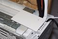
Setting out a drilling template

Marking out the wall for the large hole
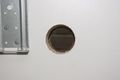
Tapered hole sloping downwards
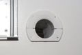
Hole trimmed by plastic cylinder and end flange
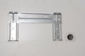
Completed wall preparations for indoor unit


Installation onto Wall Bracket

The wall bracket is made from a pressing of relatively thin sheet steel. The bracket is strong enough to hold the 10 kg of indoor unit, but the two lugs for hanging the unit moved outwards while I manoeuvred the unit into place. So my indoor unit is hanging about two millimetres away from the wall at the top. I also cut a rebate out of the bottom of the enclosure of indoor unit, to let the unit touch the wall at the bottom.
If I had a second pair of hands I would look at putting some shims into the lugs on the wall bracket, but the indoor unit is quite an unwieldy thing above your head (especially with no headroom!) and with it sitting on its bracket I decided it was best to leave it there. Bearing in mind the unit is for installation close to a ceiling, I do wonder if a pair of simple screw lugs with keyhole slots (like glass plates) would make for an easier design. Anyway, with this done the only difficult part of the job was over.
Copper Pipes


The next task is to form the copper pipes poking out through the wall into shapes to meet the long pipes linking to the outdoor unit. The pipes are easy enough to bend as long as you take your time. The technique is to apply an even pressure with all fingers and both thumbs, then move along 15 mm or so and repeat, and so on. The larger pipe is more difficult to bend, so it is sensible to form this one first to the best shape you can, and then bend the smaller pipe to match.
The plastic pipe covers are still in place here to keep the pipe connections as scrupulously clean as I can manage. The machined conical connections are behind them, with the pipe flares on the long pipes to connect to them. The black foam insulation is pulled away to let me manipulate the pipes into place and is tied into place later. The white pipe is the drain pipe, located at the bottom of the bundle to make sure it drains correctly, and the black cable is the control cable.
The kit omits all the hardware to attach the pipes to the outside of the building. I guess, every installation is different, and every DIY person has their own idea of what is “proper”, and so I made my start by looking at some professional air conditioner installations outside factories and shops and so on. My intention being to make something reasonably business-like without crushing the insulation on the pipes or spending a fortune on a tiny quantity of cable tray or “Unistrut” or custom pipe brackets.
I settled on some lengths of hardwood screwed to the building, with the pipes and cable secured in metal P clips with rubber inserts. This gives a stand-off between the pipes and the wall – and this in turn makes for a more gentle swan neck at exit of the pipes from the wall an easier task to manipulate the pipes into place. Also I can get a paintbrush under and around the assembly when the time comes to top-up the finish on the building cladding. This is how the brackets looked to begin with, before I routed the drain pipe into my water butt (described later).
The two long pipes arrive coiled up. I want a fairly sharp bend at the outdoor unit, so I left the curves at this end as supplied in the kit while I loosely uncoiled the rest of the lengths.
A fresh correspondence with the supplier confirmed that it is fine to run the pipes both downwards and upwards between the indoor and outdoor units. This lets me take the easiest route for them – down the wall behind the building, through the void under the floor, and then up again and finally down to reach the valves on the outdoor unit. I began with the thicker pipe again, first creating the straight run to drop down the wall, and then forming a curve to take the pipe around and into the floor void. With the first half of this pipe in place I made off its connection to the short pipe from the indoor unit, and then formed new bends and made off its connection to the outdoor unit.
When you remove the first plastic cap from a pipe on the indoor unit, you lose the last of its factory pressurisation, and it seems sensible to then assemble the joint promptly to avoid the ingress of any dust or dirt. I do not possess many large spanners but by chance I found both 17 and 22 mm open-ended ones, and these let me tighten the pipe fittings with the confidence you get with a conventional spanner. The fittings are lightly oiled before assembly, and then assembled to make a gas-tight seal. Effectively you are crushing and deforming a copper flange (the flare) against a conical surface to make each joint, so clearly the joints really do need to be very tight indeed. The installation manual suggests, “as tight as a car wheel nut”, and I suggest, possibly a little tighter. The last thing you want during this activity is for a spanner to slip and you to take the skin off your knuckles, so I suggest a couple of decent spanners are better than adjustable ones. Ordinary spanners are also likely to be longer than adjustable ones, which helps you to feel the tightness as you go along.
The smaller pipe is easier to run in, and just as hard to connect, but the result looks nice to me. Looking at the ends of the pipes at the outdoor unit, the grey insulating sleeving here is supplied as one piece in the kit, but it makes for a neater job to cut it and apply two short lengths.
Electrics
The remaining nerve-wracking part of the job is making off the earth connection at the outdoor unit. Let it suffice to say, the earth wire in the control cable has a fitted ring lug, and so you have to remove the screw from its terminal; the screw is close above a hole in the enclosure, and if that screw goes down inside it will be there forever. I kept hold of mine. The other three wires in the control cable have simple fork lugs.
Setting Up


With the pipes and the wiring all assembled, the time comes to set up the system. Essentially, you use a small shot of the refrigerant from the outdoor unit to pressurise the system. Check for leaks at every joint using soapy water. Then expel the air from the system, and check for leaks again. And finally fill the system with all of the remaining refrigerant, and do a third check for leaks. I had one leak, which I found on the first round, and nipping up the joint with the spanner sorted it out. This was the smaller pipe at the outdoor unit. When I tightened the joint, I watched the enclosure of the unit bow out and then relax itself.
And so, with the control cable and the pipes connected up, it is time to try everything out. The indoor unit plugs into a 13A socket and, when you press the power button on the remote control, the display obligingly lights up and the machine opens its air flap. Seeing everything start up and run for a couple of minutes, I shut it down and tidied up the installation with foam insulation around the ends of the copper pipes and putting the access cover back onto the outdoor unit.
Then I restarted the system and ran it flat out as instructed in the installation manual - maximum chill for 35 minutes, and then maximum heat for as long again. The “new car smell” returned to the room for an hour or so, and then faded away. The initial impression of performance exceeds my expectations. With the ambient temperature outdoors sitting around 23 to 24C, this activity took the temperature at the far side of the room (opposite the indoor unit) down to 18C and then up to 24C. That is to say, a 6 degree increase in 35 minutes, which seems promising for next winter. During this time, the relative humidity in the room went up to 90% and down to 48%.
Finishing Off

The kit comes with a roll of nylon tape (about 50 mm wide) with instructions to wind this along the length of the two copper pipes. I cannot work out what great good this does, and with the tape being of a non-adhesive kind I decided early on that it and me were not going to get on.
I wrapped the pipes in duct tape for the first 300 mm or so after they emerge through the wall, cutting off the cable ties shown in my earlier photographs as I went along. I used white tape to blend in better with the pipe insulation and because it might (tentatively) be more thermally efficient than black. The argument here being the opposite of the one which tells you to paint your central heating radiators matt black. It is worth remembering to wind the tape on from the bottom going upwards, so water cannot run down inside it. The gap around the end of the plastic cylinder is sealed with glazier’s putty, this is hugely easier to work with than silicon and is the sealant recommended by the supplier of the system.
I ended up with the gas pipes a near-perfect length and the control cable about 150 mm shorter than I really wanted. I used up some of the cable to make a drip loop below its terminals on the outdoor unit, and the shortage is something I shall have to live with.

If I am to believe what I read, the condensate drain pipe can run off a litre of water in an hour. The water is not really good enough to make your tea, but it is fine for the car screen washer or the garden, so I routed the pipe across to my water butt. My idea is, when the weather is warmest and the rainfall is the least, the run-off from the system will replenish the butt. Looking again at this photograph, a real perfectionist might use some black pipe to blend in better with the rainwater drain and (just round the corner) the power supply cable for the building.

One job leads on to another. In my case, the water butt has never had an overflow pipe - any excess rainwater has simply run over the top to soak away into the ground below. This was fine before the air conditioner project, but putting the outdoor unit next to the butt suggested an overflow pipe would be prudent.
The pipe is a corrugated plastic one, marketed for use with fish and pond pumps and with an internal diameter of 21 mm. It looks like electrical conduit to me. This size of pipe can use the same P clips as the insulated pipes for the system. This about 3 metres long, and it carries the surplus rain away to the driveway. During a downpour, I recorded 12 mm rainfall in 12 minutes. The area of the roof is 12 square metres, so the rate of 1 mm rain per minute represents 12 litres per minute through the downpipe and, with the butt already full, through the overflow pipe. The overflow pipe handled this without trouble, and this is the heaviest prolonged rainfall I have ever seen here. For comparison, the water main supplying my house delivers about the same rate through a 15 mm bore copper pipe.
App

The system boasts “Wi-Fi” and the manufacturer provides an app for you to download onto a smartphone. The Android version of the software is not approved by Google and the list of permissions is too extensive for my taste. There are two further pages of permissions, and they seem to include most every permission available to any Android app.
I did install the software for a few minutes, but it does not seem to be a functioning product. Certainly, it does not correlate with the instruction manual shipped with the kit, and I was quite relieved to decide to uninstall it.
Operation
First Impressions
The outdoor unit rattled a bit during the initial soak test I describe above. I didn’t notice when this noise stopped but I guess it is to do with the refrigerant spreading itself out through the system. I installed the system in July 2017, when the ambient temperature ranged from about 28C in full shade down to 16C at night, so I could try out the heating mode as well as the cooling mode in meaningful outside temperatures.
Functionality
You get a few extra modes of operation – the obvious cooling and heating, and also a “drying” mode, a plain “fan” and an “auto” mode. This “auto” mode instructs the system to maintain a pre-set temperature (nominally 25C) with a wider than usual tolerance, so running proceeds without the system fighting itself with alternate heating and cooling cycles. For illustration, with the ambient temperature at 16C in the middle of the night, the auto mode is keeping the room at 23C.
There are no useful operating controls on the indoor unit and all operation of my system is from the remote control or possibly the app. If the remote control gets broken, the system will be useless until a replacement is found.
Indoor Noise Levels

The marking plate on the indoor unit of my system gives maximum noise levels of 40 to 48 dB(A) indoors and 63 dB(A) outdoors. No monitoring distance is quoted, but it is usually 1 metre.
The noise levels inside my room are too low to measure using my sound level meter (range from 40 to 130 dB), but in subjective terms the indoor unit is quieter than my small laser printer (Brother HL-2035). The level of noise coming indoors from the outdoor unit is controlled by the construction of the wall, but at its loudest it is comparable to the level of sound from the fan in an electric cooker using a conventional (not fan) oven.
Environmental Impact
The greatest and most immediate environmental impact is the noise from the outdoor unit. This varies a great deal, according to how much work the system is doing.
Listening carefully, the outdoor unit is almost inaudible at its lower speeds, and I have to look at the fan to confirm that it is running. The unit gets louder when it is working harder, and with the system in its cooling mode the maximum sound pressure level I can measure outdoors is around 64 dB(A) at a location 1 m above the top of the unit and mid-way between the wall behind it and the fence in front of it. This figure correlates well with the manufacturer's declaration of 63 dB(A), which is likely to be for the unit in free space or an anechoic chamber, and allowing for reflections from the hard surfaces nearby: the wall of my building (120 mm away), my neighbour's garage (1,500 mm) and my fence (630 mm at its closest point).
I real terms, this means I can just about hear the unit if I stand 2 m away from the far side of the fence, and if I walk a further 4 m away, to the reach the nearest wall of my neighbour's house (6 m in all) the sound is on the threshold of my hearing, blending in with the rustling of leaves on trees and traffic on a trunk road 800 m away.
If you need to minimise noise, for example for the sake of people nearby, you can minimise the projected noise by installing the outdoor unit at ground level (as opposed to part way up a wall), and it seems sensible to arrange the fan to point along a boundary rather than across it. Fences stop the sound going horizontally, but it will then go upwards.
The refrigerant in the system is R-410A, which is the preferred refrigerant for residential air conditioners in Europe. R-410A does not contribute to ozone depletion, but it still has a high potential for global warming. R-410A facilitates a respectable SEER rating of 6.1 for my system, this will bring a relatively light demand for the electrical power supply.
Performance
Subjective Observations
The paper specifications of my system and of many others advise that the temperature demanded for room heating must be 8C or more above the outdoor temperature, and the temperature for cooling must be 8C or more below the outdoor temperature. In practice, the system seems to work fine with much smaller temperature differentials, so I imagine the specifications exist to define the conditions for peak efficiency or perhaps to cover the manufacturer against claims of imprecise temperature control.
The cooling mode creates a gentle de-humidifying action even when the demanded temperature is about the same as the natural room temperature. Room heating is far quicker than a radiant electric heater - the system introduces more heat (2.6 kW opposed to 1 kW) and it blows the warmed air around the room too.
Context of Performance Logs
For my system, the room has a high level of thermal insulation (as good as a house built in the mid-2000's) but its structure has a much lower thermal capacity. The walls will not store as much heat to radiate into the room during unheated periods, and the air in the room will cool down much more quickly than the air in a comparable brick-built structure. Conversely, the roof of the building is in a clear space exposed to sunlight throughout the year, and has a dark matt finish which absorbs heat better than it radiates heat.
The size of my room is about half of the maximum specified for the system:
- The room measures 3.0 x 3.5 metres, so 10.5 square metres in all.
- The ceiling slopes across the room and has a mean height of 2.17 metres, so 22.8 cubic metres in all.
Finally, the room has a source of heat - me - for all or most of the time, which needs to be factored into the results.
Heating and Cooling during Summer

My location can experience a surprisingly high diurnal temperature range in summer. This first log shows the heating performance of the system on a mild but hardly warm August morning. I ran the system for two hours with the door and window of the room open to make the system run reasonably hard.
- The demand temperature was 25C.
- The rate of temperature rise achieved surpasses anything I have ever achieved using an oil-filled radiator.
- I did not hear the system running. When I looked at the outdoor unit, the fan was rotating at its slowest speed.
- The outdoor temperature sensor is beside the door frame, and the outdoor temperatures logged here may be distorted by warmed air leaving the room.

The second log shows the cooling performance of the system mid-afternoon, when the temperature indoors is already lower than outdoors, and the outdoor temperature is still rising and then falling. The door and windows are wide open to the garden.
- The demand temperature was 16C
- The building was in full sun, but sunlight did not reach the door or window apertures
- During this run, the relative humidity in the room remained almost constant - it began at 53% and ended at 51%

A year later, the third log shows how well the system cools the room when the outside temperature is falling.
- The demand temperature was 20C, and the window was open throughout.
- There is a tiny overshoot at the end of the log, but in practical terms the system achieved comfort quickly on an unpleasantly hot and humid evening. This was an evening during July or August 2018.
I also ran the system through a night to see how the system could control the temperature using its cooling mode. The door was shut and the window was open a little, to allow a trickle of fresh air into the room.
- The demand temperature was 21C
- The duration of the test was 9 hours
- The fan on the indoor unit was on its lowest setting
- The indoor temperature remained around 20C, while the outdoor temperature dropped from 22.0C (start) to 15.7C (end)
- Humidity indoors began at 55% and had risen to 70% by morning
It is difficult to know how much of this result reflects the insulation of the building, but the system achieved a temperature barely 1C away from the demand temperature, even though the ambient dropped rather lower than the demand, and the temperature differential was always less than the 8C cited as a minimum in the specifications. Afterwards, I opened the door for an hour - the indoor temperature dropped to 19C (demand still 21C), the outdoor had risen to 17C, and the fan on the outdoor unit had not run.
Heating during Autumn
The structure of the garden building holds less heat than a brick-built house, and so the room needs comfort heating a little earlier in the year. By late October, the unheated room can drop to around 9C overnight, being about 2C above the temperature outdoors.
I ran the system for two hours with the door and window of the room closed, to make the heating performance representative of what I would usually encounter.
- The demand temperature was 20C.
- With the door shut, the outdoor temperatures logged here should be independent of the heating indoors.

The heating effect from a heat pump is very different to the heating from a central heating radiator or a radiant electric fire - there is a near-instantaneous blast of warm air. In practice, this means the room reaches a bearable temperature for use as a personal office within a few minutes of starting the system.
Limits of Cooling Compliance
With the outdoor temperature at 28.7C, the door and window open to the garden and the fan of the indoor unit set to its lowest speed setting, the system was keeping the indoor temperature at 23.6C.
- The demand temperature was 21C (close to the specification requirement of 8C below ambient)
- When I set the fan to its automatic setting (by which the system chooses one of its three fan speeds), this achieved no additional activity
- When I returned the fan to its lowest speed setting, and closed the door and window, the system reduced the indoor temperature to 22C in less than 20 minutes
The system seems to monitor the results of its efforts quite closely, and only increases its efforts if it senses it can use them to make a practical effect.
Heating during Winter

Heating the room during the winter months was my the main reason for installing the system in the first place, and I have written up this section at the end of the first winter for the system.
During cold weather, thin deposits of frost form across the heat exchanger at the back of the outdoor unit, but they do not seem to affect the operation of the system. I imagine, the deposits are encouraged by the chilled air blowing through the heat exchanger when the system is heating the room. The frost usually forms at night, when the temperature drops near or below freezing, and then clears away the next day when the temperature rises again.
Snow can remain on the top of the outdoor unit as easily as on other surfaces, and this happened three times during this first winter. On the first occasion, the melting snow became a chunk of ice on one the end of outdoor unit (photo). The system continued to run without difficulty, but I became a little anxious.
This particular system has a frost protection feature. The operation of this feature is not described in the user manual, but I understand what it does is to reverse the operation of the heat pump for a short time, and use heat from the room to defrost the outdoor unit. I did not have enough patience to wait for the feature to start, and so I shut down the system. I used a hot air gun to remove most of the ice, and left the system switched off overnight to let the rest of the ice clear away. I restarted the system to heat the room the next day, but the activity left me without use of the system for 15 hours or so.
I usually set the temperature demanded to its lowest setting of 16C, and the system delivered this most of the time. During exceptions, the temperature achieved was always higher than what I had asked for, usually by 2C. Typically, the system managed 16C when the room was empty, rising to 18C when I was in it.
The frost protection feature is not constrained by the 16C lower limit which applies during normal operation. The winter of 2017/18 was one of the coldest for some years in this location, but temperatures never dropped low enough (or perhaps, for long enough) to make the system shut down or trigger its frost protection feature.
Operation during Spring
With the system set to provide heating, the temperature compliance worsens when the outdoor temperature rises above about 10C. This behaviour tallies with the specification of the system, which needs a temperature differential of at least 8C between outdoor and indoor temperatures, and 16 - 10 = 6C.
During the shoulder season, when the outdoor temperature has reached around 14C (and a little too cold for comfort) the system will tend to heat the room to be rather too warm, around 22C. There is then a choice between using the system to heat the room with the window open to retain comfort; or using a radiant electric heater instead. I suspect, running the system with the window open uses less electricity.
By the time the outdoor temperature has reached 22C, the indoor temperature is about the same and the system (still set to a demand of 16C) simply stops running.
Final Thoughts
My system came with two 4-metre lengths of pipe to run between the indoor and outdoor units. You can buy a pair of extension pipes, and the system has enough refrigerant to let you have 6 metres of pipe instead of 4 metres. Beyond this you will need professional help to purge and charge the system, and you would probably save money by buying a system without refrigerant.
You need to have good clear access to the pipe fittings so you can tighten them up correctly and inspect them while you are setting up the system for operation. The space behind my building is fairly confined – I have 450 mm of access space – and I suggest this is a practical minimum if you are going to preserve the skin on your knuckles and elbows while you get the pipes into place.
If the pipes are to go out through the left-hand end of the indoor unit, you will have two pipe joints hidden inside the back of the unit and impossible to inspect during setting up. If you really need to choose this pipe route then installation is probably best left to a professional who can test the pipe work for its gas tightness in stages, without wasting refrigerant and before hanging the unit onto the wall.
When I peeled the protective film off the front of the indoor unit I found a scratch I had made during manhandling. It doesn’t show badly, but it is there to remind me to get help with installing this sort of unit if I tackle a second system.
The Android app seems to be unworkable and although this is of no consequence to me it could be a major disappointment to someone who chose a particular system on the strength of this feature. Perhaps the iPhone version is better.
The electric motors in the system present an inductive load which will (as an inductance) prove reluctant to turn off in an electromagnetically clean sort of way during normal operation. My nearby computer equipment is powered from the same ring but through an uninterruptable power supply which gives some filtering. I do not envisage problems here, but a person with a sensitive hi-fi system (and perhaps an equally sensitive disposition) might look to run in a dedicated radial circuit from the consumer unit.
The use of a 13A plug in a wall socket leaves me with the supply cable draped across the wall, and I can see the insertion of a fused connection unit into the ring as a future project for myself. Other possible trimmings for my own system are some mesh around the void under the building to keep out rats (I live near a train station …) and a roof over the outdoor unit to shield it away from direct sunlight. I save seen such roofs in the Mediterranean and the Middle East, but not in England, and I’m inclined to think this is unnecessary for me.

The initial result, with the system running as a heat pump in mid-July, is not quite what I intended for the season but is a good result all the same. The most compelling attribute of the system to me is its quietness of operation. There is even a “quiet” mode to reduce airflow from the indoor unit, and this kind of system seems good for a bedroom as well as a room for studying.
Technical Specifications
The technical specifications let you identify the requirements for the electrical power supply and help to provide a context to assess the performance of the system. Unfortunately I have encountered five sets of technical specifications for my system: the web site (from which I placed my order); the technical manuals; the energy efficiency label; some sales literature from the vendor; and the marking plate attached to the indoor unit.
There are minor discrepancies across these sources ... I have no way of telling which parameter values are correct, and so for the sake of consistency I use the details from the marking plate where they exist. The parameter values given in sets of three here seem to be nominal, minimum and maximum values.
Cooling capabilty
Pdesignc: 2,500 W (this is the declared cooling load)
Cooling capacity: 2,500 W (1,500 to 3,300 W)
Cooling power input: 780 W (380 to 1,200 W)
Cooling current input: 3.5 A (1.6 to 5.4 A)
Heating capability
Pdesignh(A) 2,600 W (this is the declared heating load - it should be the rated heat output of the heat pump heater at the reference design temperature, but the reference design temperature is not declared)
Heating capacity: 2,600 W (1,300 to 3,400 W)
Heating power input: 720 W (390 to 1,200 W)
Heating current input: 3.3 A (1.7 to 5.5 A)
Electrical power requirements
Rated voltage: 220 to 240V
Rated frequency: 50 Hz
Rated current input: 9.0 A (this is the expected inrush current, which occurs when one of the motors starts)
Rated power input 1,600 W (this is probably the peak real power needed for what is essentially a very inductive load, and which occurs with the inrush current)
Other items
Indoor discharge air flow: >= 500 m3 /hour
Indoor/outdoor noise: 40 to 48/63dB(A)
The energy efficiency ratio (EER) does not appear on the marking plate, but is given on the energy efficiency label.
Referenced Standards and Regulations
Building regulations
HM Government, The Domestic Building Services Compliance Guide
Published in 2013 by NBS (part of RIBA Enterprises Limited), and effective from 6 April 2014 for use in England
Section 10.2, Aircooled and water-cooled air conditioners
Planning regulations
The Town and Country Planning (General Permitted Development) (Amendment) (England) Order 2011
Class G [gives the conditions for the installation, alteration or replacement of an air source heat pump as permitted development]