Difference between revisions of "Vaillant Ecotec plus 624 repair"
m (→Diagnosis: typo) |
|||
| (11 intermediate revisions by the same user not shown) | |||
| Line 1: | Line 1: | ||
| − | ==Overview== | + | This article is a collection notes on various repairs carried out on this boiler over the years. |
| + | |||
| + | ==Main Heat Exchanger Replacement== | ||
| + | ===Overview=== | ||
This is a quick overview of the procedure I followed to replace a leaking main Heat eXchanger (HX) in a Vaillant Ecotec plus 624 system boiler. (the procedure would be much the same for many Vaillant boilers made in the last ten years or so). | This is a quick overview of the procedure I followed to replace a leaking main Heat eXchanger (HX) in a Vaillant Ecotec plus 624 system boiler. (the procedure would be much the same for many Vaillant boilers made in the last ten years or so). | ||
| Line 5: | Line 8: | ||
This is not intended as a primer in boiler repair. It is assumed that you are competent to do this kind of work and have the required skills and tools. If in doubt call a professional! See the [[Boiler repair]] article for more guidance. | This is not intended as a primer in boiler repair. It is assumed that you are competent to do this kind of work and have the required skills and tools. If in doubt call a professional! See the [[Boiler repair]] article for more guidance. | ||
| − | ==The problem== | + | ===The problem=== |
Over a period of time the central heating system had been showing slow pressure loss. This had got to the point were a litre or more was being lost per day. This is obviously not good, since it could mean loss of water into the fabric of the house and the possibility of supporting dry or wet rot, or damage to decorations etc. Its also not good for the heating system since one is introducing fresh water all the time, and hence more oxygen (so more corrosion) and hard water scale. | Over a period of time the central heating system had been showing slow pressure loss. This had got to the point were a litre or more was being lost per day. This is obviously not good, since it could mean loss of water into the fabric of the house and the possibility of supporting dry or wet rot, or damage to decorations etc. Its also not good for the heating system since one is introducing fresh water all the time, and hence more oxygen (so more corrosion) and hard water scale. | ||
| − | ==Hunt the leak== | + | ===Hunt the leak=== |
There were no stains on the ceilings downstairs, so it seemed unlikely it was the upstairs radiator piping. Checking things like the drain point outside and also the pressure relive blow off pipe for leaks (small plastic bag fixed over the ends), again found nothing. So then, several days spent getting under the downstairs floors, creeping around the crawl space, and ... nothing - it all looked good. | There were no stains on the ceilings downstairs, so it seemed unlikely it was the upstairs radiator piping. Checking things like the drain point outside and also the pressure relive blow off pipe for leaks (small plastic bag fixed over the ends), again found nothing. So then, several days spent getting under the downstairs floors, creeping around the crawl space, and ... nothing - it all looked good. | ||
| Line 15: | Line 18: | ||
So we have a culprit, now all we need is some warmer weather! | So we have a culprit, now all we need is some warmer weather! | ||
| − | ==Parts== | + | ===Parts=== |
| − | I found a really good local(ish) [https://boilerrecycling.co.uk/ company] that had the right reconditioned part in stock (it seemed excessive putting a £400 new part in a 7 year old boiler). The were also able to advise on the exact part needed, and quickly fixed an omission from the order with no fuss and next day delivery. For the fix I needed the HX itself, plus a new main gasket for the burner (needs replacing every time you remove the burner) and the kit of extra bits like the nuts for fixing the burner (also need replacing every time since they have a "one time only" insert to lock them in place). Plus other washers etc as might be required. | + | I found a really good local(ish) [https://boilerrecycling.co.uk/ company] that had the right reconditioned part in stock (it seemed excessive putting a £400 new part in a 7 year old boiler). The were also able to advise on the exact part needed, and quickly fixed an omission from the order with no fuss and next day delivery. For the fix I needed the HX itself, plus a new main gasket for the burner (needs replacing every time you remove the burner) and the kit of extra bits like the nuts for fixing the burner (also need replacing every time since they have a "one time only" insert to lock them in place). Plus other washers etc as might be required. (The seal and fixings etc usually all come together in package as Vaillant part number 0020038679) |
| − | ==Procedure== | + | ===Procedure=== |
This is relatively straight forward if taken step by step. Aided by a very good internal design and parts layout. However it makes sense to take lots of photos of connections and wire routings etc in case you need them for reference later. | This is relatively straight forward if taken step by step. Aided by a very good internal design and parts layout. However it makes sense to take lots of photos of connections and wire routings etc in case you need them for reference later. | ||
| − | ===Isolation and Draining=== | + | ====Isolation and Draining==== |
For this job the boiler needs to be drained (although not the whole heating system), power turned off, and the gas shut off. The valves on the bottom of the boiler where the pipes enter will allow all services to be turned off, and also there is a drain point for the boiler itself). | For this job the boiler needs to be drained (although not the whole heating system), power turned off, and the gas shut off. The valves on the bottom of the boiler where the pipes enter will allow all services to be turned off, and also there is a drain point for the boiler itself). | ||
| − | ===Entry=== | + | ====Entry==== |
Slackening the single screw on the bottom edge of the front panel allows that to be removed once the two metal spring clips are depressed to free the panel. That then lifts off the top of the case. You can also pull the plastic decorative cover plate off the base of boiler at this stage. | Slackening the single screw on the bottom edge of the front panel allows that to be removed once the two metal spring clips are depressed to free the panel. That then lifts off the top of the case. You can also pull the plastic decorative cover plate off the base of boiler at this stage. | ||
| − | ===Disassembly=== | + | ====Disassembly==== |
| + | ('''Click pictures for larger versions''') | ||
| + | |||
First remove the plastic air duct - this is a push fit into the burner / fan assembly, and is retained by a single screw into a bracket at the top of the boiler. | First remove the plastic air duct - this is a push fit into the burner / fan assembly, and is retained by a single screw into a bracket at the top of the boiler. | ||
| − | Next taking | + | [[image:EcoTec+_624_AirIntakeOff.jpg|480px]] |
| + | |||
| + | Next taking off the left hand side panel (two screws, one at top and bottom) makes access easier. | ||
Also the expansion vessel can be removed - undo the single union nut at the inlet pipe, and remove two screws on the very top of the boiler to free to top retaining bracket. The part then slides forward. | Also the expansion vessel can be removed - undo the single union nut at the inlet pipe, and remove two screws on the very top of the boiler to free to top retaining bracket. The part then slides forward. | ||
| + | |||
| + | [[image:EcoTec+_624_ExpansionChamberConnection.jpg|480px]] | ||
Next disconnect the wires to the burner fan assembly, and also those to the HX itself; the ignition feed and earth wire, and the connection to the fusable link at the top of the HX (these HX have a emergency fuseable link to prevent a catastrophic melt down should the boiler fire for any length of time with no water in the HX). | Next disconnect the wires to the burner fan assembly, and also those to the HX itself; the ignition feed and earth wire, and the connection to the fusable link at the top of the HX (these HX have a emergency fuseable link to prevent a catastrophic melt down should the boiler fire for any length of time with no water in the HX). | ||
| + | |||
| + | [[image:EcoTec+_624_HXFuseableLink.jpg|480px]] | ||
Now disconnect the union nut on the flexible corrugated gas inlet to the burner. | Now disconnect the union nut on the flexible corrugated gas inlet to the burner. | ||
| Line 41: | Line 52: | ||
Next we need to free the HX from its pipework. There is a hose clip on the flexible plastic hose to the condensate trap. Loosen this, and pull the pipe off the spout. You can also pull the pipe from the condensate trap, and set that aside. | Next we need to free the HX from its pipework. There is a hose clip on the flexible plastic hose to the condensate trap. Loosen this, and pull the pipe off the spout. You can also pull the pipe from the condensate trap, and set that aside. | ||
| + | |||
| + | [[image:EcoTec+_624_HXPipeConnections.jpg|480px]] | ||
Next the main CH feed and return push fit connections need to be freed. First remove the metal retaining clips on the base of the HX. These pipes will usually have a little wiggle room, and you can pull them free slightly at this stage, even if not get them out completely. | Next the main CH feed and return push fit connections need to be freed. First remove the metal retaining clips on the base of the HX. These pipes will usually have a little wiggle room, and you can pull them free slightly at this stage, even if not get them out completely. | ||
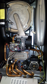
| + | [[image:VaillantEcotec824HE.png|right|thumb|200px|Note less access space due to plate HX on combi version]] | ||
Now the main HX itself can be removed (take care, its heavier than it looks). Undo the retaining nuts in the clips at the front. For ease of access I also unscrewed the retaining brackets from the back wall of the boiler as well. You now need to rotate that whole HX a little bit clockwise, so as to simultaneously pull the pipe connections up off the feed and return pipes, and also pull the main flue connection down from the flue terminal spigot (also a push fit). Once free the HX will come out. | Now the main HX itself can be removed (take care, its heavier than it looks). Undo the retaining nuts in the clips at the front. For ease of access I also unscrewed the retaining brackets from the back wall of the boiler as well. You now need to rotate that whole HX a little bit clockwise, so as to simultaneously pull the pipe connections up off the feed and return pipes, and also pull the main flue connection down from the flue terminal spigot (also a push fit). Once free the HX will come out. | ||
| − | You can also remove the condensate syphon at this stage for cleaning. First withdraw the trap from under the boiler with a partial anticlockwise twist to unlock it, then pull it down and out. The syphon itself can be freed from the base of the boiler by pushing in on the three retaining lugs under the boiler while pulling it up. Lastly you need to wiggle the syphon out of the boiler (this is the one slightly sub optimal bit of design since you cant simply lift it up as the pipe to the pump is in the way). I found that by rotating it 90 degrees anticlockwise, and then prising it leftwards behind the pump, it was possible to free it. Note if doing this on one of the 800 series combi boilers, its probably just simpler to disconnect the pipe to the pump, since the secondary hot water HX will be in your way on these models). | + | You can also remove the condensate syphon at this stage for cleaning. First withdraw the trap from under the boiler with a partial anticlockwise twist to unlock it, then pull it down and out. The syphon itself can be freed from the base of the boiler by pushing in on the three retaining lugs under the boiler while pulling it up. Lastly you need to wiggle the syphon out of the boiler (this is the one slightly sub optimal bit of design since you cant simply lift it up as the pipe to the pump is in the way). I found that by rotating it 90 degrees anticlockwise, and then prising it leftwards behind the pump, it was possible to free it. Note if doing this on one of the 800 series combi boilers, its probably just simpler to disconnect the pipe to the pump, since the secondary hot water HX will be in your way on these models). |
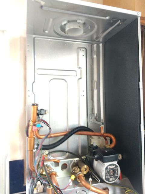
| − | ===Servicing=== | + | [[image:EcoTec+_624_Empty.jpg|480px]] |
| + | |||
| + | ====Servicing==== | ||
There are a couple of service jobs that can be done at this stage. The first is to sweep any dust and loose stuff from the outside of burner itself with a soft brush. | There are a couple of service jobs that can be done at this stage. The first is to sweep any dust and loose stuff from the outside of burner itself with a soft brush. | ||
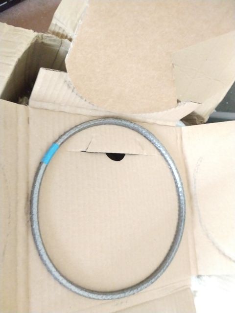
Next remove the old graphite impregnated steel mesh seal around the rim of the burner assembly by prising it out of its channel. If it has stuck to the channel at any point then carefully scrape the channel clean so the new gasket will seat correctly. Fit the new gasket, by carefully pushing it into its channel as you work around the rim. | Next remove the old graphite impregnated steel mesh seal around the rim of the burner assembly by prising it out of its channel. If it has stuck to the channel at any point then carefully scrape the channel clean so the new gasket will seat correctly. Fit the new gasket, by carefully pushing it into its channel as you work around the rim. | ||
| + | |||
| + | [[image:VaillantBoilerHXMainSeal.jpg|480px]] | ||
Since CH primary water had been getting into the condensate drain and syphon, I also gave the pipe and syphon a thorough clean - rinsing through and shaking out the closed section several times, while also using a pipe brush on the more accessible bits. | Since CH primary water had been getting into the condensate drain and syphon, I also gave the pipe and syphon a thorough clean - rinsing through and shaking out the closed section several times, while also using a pipe brush on the more accessible bits. | ||
| Line 61: | Line 79: | ||
The CH system has a Fernox TF1 magnetic / cyclone trap fitted, so I drained and cleaned this. | The CH system has a Fernox TF1 magnetic / cyclone trap fitted, so I drained and cleaned this. | ||
| − | ===Reassembly=== | + | ====Reassembly==== |
In true "Haynes Manual" tradition, this is basically the reverse of the above. | In true "Haynes Manual" tradition, this is basically the reverse of the above. | ||
| Line 80: | Line 98: | ||
Remake the gas connection to the burner, using a new fibre washer from the kit of spares that come with the main gasket. | Remake the gas connection to the burner, using a new fibre washer from the kit of spares that come with the main gasket. | ||
| − | Now remake all the wired connections to the burner / fan assembly, and also the main HX itself. (note the installer manual for my boiler does not actually match the reality in this case since it describes two connections only | + | Now remake all the wired connections to the burner / fan assembly, and also the main HX itself. (note the installer manual for my boiler does not actually match the reality in this case since it describes two connections only and not the five it actually has, however the connections are keyed and mostly colour coded - so its pretty much impossible to get them wrong) |
| − | Lastly refit the air intake duct and fix with its single screw. | + | Lastly refit the air intake duct and fix with its single screw. |
| − | ===Recommissioning / Testing=== | + | ====Recommissioning / Testing==== |
Refill the condensate trap with clean water, and fit back into the syphon. Make sure to check that it reconnects to the condensate drain pipe under the boiler, or you may end up with a wet counter top later (DAMHIK). | Refill the condensate trap with clean water, and fit back into the syphon. Make sure to check that it reconnects to the condensate drain pipe under the boiler, or you may end up with a wet counter top later (DAMHIK). | ||
| Line 98: | Line 116: | ||
Once everything looked good, I replaced all the casing, and leave it back in normal operation. | Once everything looked good, I replaced all the casing, and leave it back in normal operation. | ||
| − | ===Final tidy up=== | + | ====Final tidy up==== |
| − | After a couple of days the system pressure was still good, so no more leak! I added fresh fernox x100 inhibitor to the system (using the TF1 as a handy place to pour it in ( you need a couple of goes to get the whole 1L in there)). | + | After a couple of days the system pressure was still good, so no more leak! I added fresh fernox x100 inhibitor to the system (using the TF1 as a handy place to pour it in (you need a couple of goes to get the whole 1L in there)). |
| − | + | ===Post Mortem=== | |
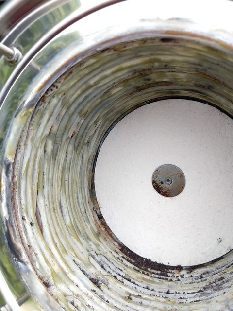
| + | Interesting to look at the failed HX: | ||
| − | + | [[image:EcoTec+_624_OldHX.jpg|480px]] | |
| + | |||
| + | Plenty of hard water scale on there from the leaking primary CH water. Hard to see any exact failure point however. Since a trip to the tip was beckoning, and life is too short to waste much time identifying the exact failure its not easy to tell what caused the initial problem after only 7 years on a system that was well cleaned and has been well maintained with inhibitor etc. Ironically the salvaged replacement part used was actually two years older than the original. | ||
| + | ===Reference=== | ||
| + | ===Part numbers=== | ||
| + | The boiler's rating plate. Note there are a number of variations of this boiler - especially in the suffix after the final "/": | ||
| + | [[image:BoilerRatingsPlate_(Medium).jpg|480px]] | ||
| + | and the main Giannoni HX - as used in many makes of boiler and across the Vaillant range. The GM30-45 bit seems to be the important part or the nummber, the 006-13 seems to vary a bit. The 24kW boiler uses the version with 5 parallel water loops, the lower powered ones have the slightly less deep version with only 4. (its the parallel paths that make it very difficult to flush blockages from these HX). | ||
| − | |||
| − | |||
| − | |||
| − | |||
| − | |||
| − | |||
| − | |||
| − | |||
| − | |||
[[image:VaillantBoilerHXModel.jpg|480px]] | [[image:VaillantBoilerHXModel.jpg|480px]] | ||
| + | |||
| + | == Main PCB replacement == | ||
| + | |||
| + | === Overview === | ||
| + | [[File:Ecotec+ Main PCB Original.jpg|thumb|400x400px|The main PCB with the top of the electronics box removed. A hybrid board with mains entering at the top right, feeding into the front panel switch and fuse. The HT transformer is the black lump on the right, The main switched model PSU section in the middle bottom, and then the modern digital surface mount processor and interface logic on the left. ]] | ||
| + | This is a description of how to replace the main PCB on the boiler. | ||
| + | |||
| + | === The problem === | ||
| + | A failure to heat or do anything really! So it has just turned really cold (-7.5°C apparently), heating was running just fine on Thursday night, but come Friday morning, it is feeling a bit nippy. I glanced at the main VR470 stat / programmer / weather compensation control in the hall, expecting it to tell me all was well, and just how cold it was outside. The first indication that all was not well: it was completely blank and non responsive. | ||
| + | |||
| + | === Diagnosis === | ||
| + | So checking the [[MCB]] for the heating circuit, then the [[fuse]] in the switched fused connection unit in the airing cupboard that feeds the heating system, showed those were fine. In fact turning off that supply resulted in the motorised valves springing back to their "un powered" state. So power was definitely good. | ||
| + | |||
| + | So dive a bit deeper; I took the cover off the boiler, flipped down the electronics enclosure and took the cover off that. Using a multimeter checked the fuse there was ok. Turning the power back on, and turning the boiler back on resulted in its LCD lighting up, and the boiler started its normal power on cycle. It ran for a few seconds, and then shut-down completely. No fault code, no diagnostic message, just "off". | ||
| + | |||
| + | Now that is pretty unusual for these boilers - they have loads of built in self test, and can report a wide range of diagnostic fault codes. However to do that, they need to be turned on, and apparently this one no longer was. Powering down, waiting a bit and turning on again would result in the same result. This was looking increasing like a control system problem - and most likely a fault in the power supply section of the main PCB. As a final test, I checked that the pump was not shorting its power feed, and while I was at it made sure its impeller was able to spin freely by turning its shaft with a screwdriver (having removed the access cap on the front). | ||
| + | |||
| + | So now it looks pretty likely it is a PCB fault. I did a visual inspection of it, nothing that had obviously let out the magic blue smoke (for those unaware modern electronics runs on magic blue smoke - if you let that out it stops working!). No water damage. | ||
| + | |||
| + | It is a ten year old PCB, so my next thought was failing electrolytic capacitors. There were not that many on the board, so I then tested those in-circuit using my ESR meter. Some were slightly below marked value - but still within 15% the intended spec - so not conclusively bad. While I had most of the values in stock as spares, I did not have anything I could replace the main 100uF 400V reservoir cap with. More to the point, it was cold and getting colder, so swapping the whole board seemed like a more expedient and certain way of fixing it ASAP than romping off down the component level repair option. | ||
| + | |||
| + | So I thought; "what I need is a man in a van with a nice stash of spares". Alas a quick phone round all the local fitters as recommended on the Vaillant web site made it quite clear that it was a very busy time of the year, and a visit in the next fortnight was not going to happen. A chat with one helpful fitter was handy though since he was also convinced from the description of the behaviour that it was a PCB fault. | ||
| + | |||
| + | === Getting a replacement === | ||
| + | [[File:Ecotec+ PCB personality module.jpg|thumb|400x400px|Closeup of the personality module that needs moving to the new board]] | ||
| + | So dreams of a same day fix have now well and truly having faded, it seemed easier to order in a recon PCB. | ||
| + | |||
| + | A quick chat with Geoff at the excellent [https://www.cetltd.com/ CET Ltd], had one on order. At this point it was a case of find all the fan and other plug in heaters around the house, light the log fire, and switch on the immersion so it can do the hot water cylinder. No doubt we can hold out for a day! | ||
| + | |||
| + | This is where is started going a bit pear shaped. The next day delivery turned into next working day - so Monday. A packing error then delivered a PCB for a completely different boiler. Courier woes (something about abnormally cold weather and snow - yes tell me about it!) then extended the final delivery of the right bit by another several days! Brrrr. | ||
| + | |||
| + | I think on Wednesday it occurred to me that if this was capacitor failure, there is a quick and dirty hack that might help. Cold caps have a lower capacitance than warm ones, especially when on their last legs. If it was the main reservoir cap that was unable to deliver the power during a surge at startup, we might be able to coax some extra from it if we warm it up a bit. So I stuck the "non working" PCB back in, and set about warming the PCB with a hair drier. Then powered it back on - it started like before - but this time it carried on! Yay, warmth - it then ran all day pumping some heat back into the now thoroughly cold place. Had to do the same trick on Thursday morning, but fortunately the courier finally turned up with the missing board in the afternoon. | ||
| + | |||
| + | === Swapping the board === | ||
| + | [[File:Ecotec+ NewPCB.jpg|thumb|400x400px|New board installed. Pretty close to identical but with a slightly different HT transformer, and different colour relay near the green pump connection. ]] | ||
| + | These are very straight forward to swap out. On this revision of the PCB, all the terminations are onto connectors that can be unpluged from the board - so no need to disconnect any wires from screw terminals. Some of the connectors are "edge" connectors. These just slide off the board. The multi pole connectors are polarised, colour coded, and have a side retaining clip you need to depress to free them from their sockets. The most difficult to free is the HT lead that runs from the HT transformer on the board to the spark igniter in the boiler. This is connected via an insulated spade terminal that has a fairly tight grip on the terminal on the transformer. This can be wiggled free with a fairly firm pull on the terminal. | ||
| + | |||
| + | The board itself is retained by three plastic clips built into the enclosure - push these out of the way, while gently lifting the lower edge of the board. It will come free. It can then be "unhooked" from the clips at the top. | ||
| + | |||
| + | There is a small yellow "personality" module that is specific to the model of boiler, and it informs the PCB which boiler it is in, this also needs to be unplugged from the board and moved to the replacement. | ||
| + | |||
| + | The new board can be fitted in place and all the connectors plugged back in. | ||
| + | |||
| + | === Powering on === | ||
| + | [[File:Ecotec+ First power on New PCB.jpg|left|thumb|First power on - the boiler has spotted its new brain!]] | ||
| + | Now if the replacement board came from an identical model of boiler, that may be all that is needed. However chances are it will not have, and the control logic will spot a mismatch between the boiler's id module and the information held in the non volatile memory on the board. The boiler will power up, and display a "F.70 Fault invalid Device Code" message. | ||
| + | |||
| + | The PCB came with a Vaillant manual excerpt that listed all the models of boiler that are supported by the PCB (about 50 in total - [[:File:VaillantDeviceSpecificNumberTable.pdf|scanned copy here]]). This was split into country specific sections (each country has a different model number prefix - so there were in total 15 pages of data to cover every model in every local). | ||
| + | |||
| + | Mine was a VUW GB 246/5-5, and that needs a device code of "09". | ||
| + | [[File:Ecotec+ Setting device code.jpg|thumb|Setting the device code based on the boiler model number. (value taken from the supplied manual)]] | ||
| + | So you now need to use the boiler front panel to go into "installer mode" (hold both "i" buttons together, and select from the menu. It will prompt for the "secret" installer code - normally 17). | ||
| + | |||
| + | You can go to the Device code menu. Here you can select one of a number of device codes to fiddle with (there are many of them - use the + and - buttons to scroll up or down through the list). | ||
| + | |||
| + | The boiler will give a brief description of what each code is for. Which ones are available will depend on model and type of boiler - but these let you configure a multitude of settings like the maximum flow temperature, or the pump speed, or the overrun time, how valves and external relays etc need to be controlled). Note if you have one of the posher controllers for the boiler, like one of the weather compensator models, many of these settings can also be altered using the more wordy controls available there. | ||
| + | |||
| + | For this job we need code "D.093 - Adjust Device Specific Number", select that, and set the number to the value taken from the model lookup table - (so 09 for my boiler). | ||
| + | |||
| + | Once that is done. normal operation resumes, tada! You just need to set the date and time. (fortunately the more elaborate configuration of my multiple heating zones and other parameters is retained by the weather compensator, and not the boiler). | ||
| + | |||
| + | You can now put all the covers back on, and wait for it to decide that the hot water cylinder really needs a refresh because the lady of the house just had a shower, and that is going to take priority over heat! (not helped because this also happens to be the day I had elected to have an "anti legionella" cycle where it heats the cylinder 10 degrees hotter than normal to make sure it is completely sanitised). | ||
| + | |||
| + | |||
| + | ==See Also== | ||
| + | |||
| + | *[[Central Heating Repair]] | ||
| + | *[[Domestic Hot Water Systems]] | ||
| + | *[[Corrosion Inhibitor]] | ||
| + | |||
| + | [[Category: Plumbing]] | ||
| + | [[Category: Heating]] | ||
Latest revision as of 22:52, 7 August 2023
This article is a collection notes on various repairs carried out on this boiler over the years.
Main Heat Exchanger Replacement
Overview
This is a quick overview of the procedure I followed to replace a leaking main Heat eXchanger (HX) in a Vaillant Ecotec plus 624 system boiler. (the procedure would be much the same for many Vaillant boilers made in the last ten years or so).
This is not intended as a primer in boiler repair. It is assumed that you are competent to do this kind of work and have the required skills and tools. If in doubt call a professional! See the Boiler repair article for more guidance.
The problem
Over a period of time the central heating system had been showing slow pressure loss. This had got to the point were a litre or more was being lost per day. This is obviously not good, since it could mean loss of water into the fabric of the house and the possibility of supporting dry or wet rot, or damage to decorations etc. Its also not good for the heating system since one is introducing fresh water all the time, and hence more oxygen (so more corrosion) and hard water scale.
Hunt the leak
There were no stains on the ceilings downstairs, so it seemed unlikely it was the upstairs radiator piping. Checking things like the drain point outside and also the pressure relive blow off pipe for leaks (small plastic bag fixed over the ends), again found nothing. So then, several days spent getting under the downstairs floors, creeping around the crawl space, and ... nothing - it all looked good.
So with a bit of thinking, that only left the boiler itself. There was no obvious water near that, however being a modern condensing boiler there is one place it can leak and not be obvious - inside the primary heat exchanger. Any loss there will be directed into the condensate drain. So I turned the boiler off for a couple of hours, and emptied the condensate trap. A bit later the trap was half full again! (it should only fill when gas is being burnt). There was also some discolouration of the plastic of the trap, which is also unusual - normally the water is here is crystal clear. Taking the trap out altogether, revealed a small drip every few seconds or so.
So we have a culprit, now all we need is some warmer weather!
Parts
I found a really good local(ish) company that had the right reconditioned part in stock (it seemed excessive putting a £400 new part in a 7 year old boiler). The were also able to advise on the exact part needed, and quickly fixed an omission from the order with no fuss and next day delivery. For the fix I needed the HX itself, plus a new main gasket for the burner (needs replacing every time you remove the burner) and the kit of extra bits like the nuts for fixing the burner (also need replacing every time since they have a "one time only" insert to lock them in place). Plus other washers etc as might be required. (The seal and fixings etc usually all come together in package as Vaillant part number 0020038679)
Procedure
This is relatively straight forward if taken step by step. Aided by a very good internal design and parts layout. However it makes sense to take lots of photos of connections and wire routings etc in case you need them for reference later.
Isolation and Draining
For this job the boiler needs to be drained (although not the whole heating system), power turned off, and the gas shut off. The valves on the bottom of the boiler where the pipes enter will allow all services to be turned off, and also there is a drain point for the boiler itself).
Entry
Slackening the single screw on the bottom edge of the front panel allows that to be removed once the two metal spring clips are depressed to free the panel. That then lifts off the top of the case. You can also pull the plastic decorative cover plate off the base of boiler at this stage.
Disassembly
(Click pictures for larger versions)
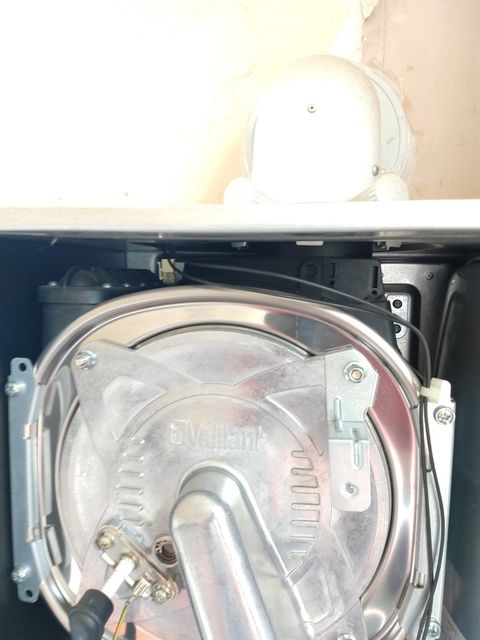
First remove the plastic air duct - this is a push fit into the burner / fan assembly, and is retained by a single screw into a bracket at the top of the boiler.
Next taking off the left hand side panel (two screws, one at top and bottom) makes access easier.
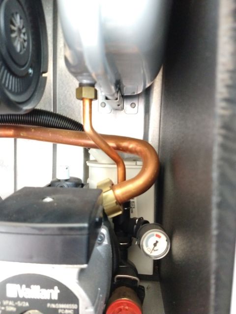
Also the expansion vessel can be removed - undo the single union nut at the inlet pipe, and remove two screws on the very top of the boiler to free to top retaining bracket. The part then slides forward.
Next disconnect the wires to the burner fan assembly, and also those to the HX itself; the ignition feed and earth wire, and the connection to the fusable link at the top of the HX (these HX have a emergency fuseable link to prevent a catastrophic melt down should the boiler fire for any length of time with no water in the HX).
Now disconnect the union nut on the flexible corrugated gas inlet to the burner.
Finally, remove the burner by removing the 4 retaining nuts on the face of it. The whole burner assembly will now pull out of the HX and can be placed safely aside.
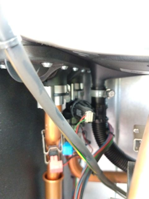
Next we need to free the HX from its pipework. There is a hose clip on the flexible plastic hose to the condensate trap. Loosen this, and pull the pipe off the spout. You can also pull the pipe from the condensate trap, and set that aside.
Next the main CH feed and return push fit connections need to be freed. First remove the metal retaining clips on the base of the HX. These pipes will usually have a little wiggle room, and you can pull them free slightly at this stage, even if not get them out completely.
Now the main HX itself can be removed (take care, its heavier than it looks). Undo the retaining nuts in the clips at the front. For ease of access I also unscrewed the retaining brackets from the back wall of the boiler as well. You now need to rotate that whole HX a little bit clockwise, so as to simultaneously pull the pipe connections up off the feed and return pipes, and also pull the main flue connection down from the flue terminal spigot (also a push fit). Once free the HX will come out.
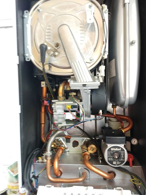
You can also remove the condensate syphon at this stage for cleaning. First withdraw the trap from under the boiler with a partial anticlockwise twist to unlock it, then pull it down and out. The syphon itself can be freed from the base of the boiler by pushing in on the three retaining lugs under the boiler while pulling it up. Lastly you need to wiggle the syphon out of the boiler (this is the one slightly sub optimal bit of design since you cant simply lift it up as the pipe to the pump is in the way). I found that by rotating it 90 degrees anticlockwise, and then prising it leftwards behind the pump, it was possible to free it. Note if doing this on one of the 800 series combi boilers, its probably just simpler to disconnect the pipe to the pump, since the secondary hot water HX will be in your way on these models).
Servicing
There are a couple of service jobs that can be done at this stage. The first is to sweep any dust and loose stuff from the outside of burner itself with a soft brush.
Next remove the old graphite impregnated steel mesh seal around the rim of the burner assembly by prising it out of its channel. If it has stuck to the channel at any point then carefully scrape the channel clean so the new gasket will seat correctly. Fit the new gasket, by carefully pushing it into its channel as you work around the rim.
Since CH primary water had been getting into the condensate drain and syphon, I also gave the pipe and syphon a thorough clean - rinsing through and shaking out the closed section several times, while also using a pipe brush on the more accessible bits.
I also checked the pressure in the expansion vessel - spot on the value (0.4 bar) shown on its label.
I carefully wiped round and checked the 'O' rings on the main feed and return connections to the HX, as well as the flue connection on the new HX and made sure the matching flue spigot in the boiler itself was also clean. A little silicone grease can aid assembly.
The CH system has a Fernox TF1 magnetic / cyclone trap fitted, so I drained and cleaned this.
Reassembly
In true "Haynes Manual" tradition, this is basically the reverse of the above.
First I replaced the condensate trap - wiggling behind the pump and twisting into place.
Before refitting the main HX, I connected the lead to the fusible link connection on the top, since this would be harder to reach once in place.
Once the HX is pushed onto the flue spigot, and down onto the push fit pipe connections, you can replace the brackets and fix it in place, and refit the clips that retain it from the front.
Now replace the spring clips that lock the feed and return pipes in place.
Push the condensate pipe onto the spout on the bottom of the HX, and tighten its clip. Push the other end into its connection on the syphon.
Now replace the expansion vessel, and refit its retaining clip. Reconnect the union nut at the bottom, taking care to make sure you have included the fibre washer.
Now refit the main burner assembly. This is retained by the 4 nuts on the face of the burner. Remember to refit the bracket that holds the air duct under the top right fixing. The nuts have a positive end stop when tightening.
Remake the gas connection to the burner, using a new fibre washer from the kit of spares that come with the main gasket.
Now remake all the wired connections to the burner / fan assembly, and also the main HX itself. (note the installer manual for my boiler does not actually match the reality in this case since it describes two connections only and not the five it actually has, however the connections are keyed and mostly colour coded - so its pretty much impossible to get them wrong)
Lastly refit the air intake duct and fix with its single screw.
Recommissioning / Testing
Refill the condensate trap with clean water, and fit back into the syphon. Make sure to check that it reconnects to the condensate drain pipe under the boiler, or you may end up with a wet counter top later (DAMHIK).
Now turn on the gas service valve, and check the connection to the main burner is gas tight with some leak detection spray.
Turn on the feed and return service valves, and ensure there are no leaks from the connections to the HX.
Next I opened the CH drain point a bit, and refilled at the service loop - this allowed all the air to be pushed out of the boiler. Then I closed the drain point. Next I set the system pressure to be "adequate" using the small internal pressure gauge (you can't see the more accurate digital one until the unit is powered).
To be sure that the boiler was properly bled of air, I turned off the gas inlet tap to make sure it could not fire, and powered on the boiler. Pushing the flame stop button early on in the power up, prevents the boiler from trying to fire (and even if it did, there is no gas anyway, so it would lock out with an ignition failure code). Now enter the "installer mode" from the menu on the boiler's control panel, enter the installer code (typically 17 unless you have changed it), and go into the test programs menu. Selecting program P.0 will enter the "Bleeding test program" - i.e. it will just run the pump. Now you can set the system pressure and bleed all the rads etc (even if not fully drained there is a fair chance there is air in the system just because of the leak). Once fully purged of air, I shut it all down again, and turned the gas back on. This time allowing it to do its normal "proving" and ignition on power up. So far so good. Then since it was a very warm day and there were no heating demands, I used the test programs to run the system first on minimum load, and then full load. Again checking for any leaks or unexpected behaviour.
Once everything looked good, I replaced all the casing, and leave it back in normal operation.
Final tidy up
After a couple of days the system pressure was still good, so no more leak! I added fresh fernox x100 inhibitor to the system (using the TF1 as a handy place to pour it in (you need a couple of goes to get the whole 1L in there)).
Post Mortem
Interesting to look at the failed HX:
Plenty of hard water scale on there from the leaking primary CH water. Hard to see any exact failure point however. Since a trip to the tip was beckoning, and life is too short to waste much time identifying the exact failure its not easy to tell what caused the initial problem after only 7 years on a system that was well cleaned and has been well maintained with inhibitor etc. Ironically the salvaged replacement part used was actually two years older than the original.
Reference
Part numbers
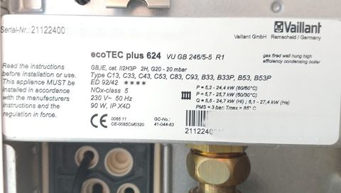
The boiler's rating plate. Note there are a number of variations of this boiler - especially in the suffix after the final "/":
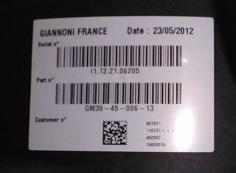
and the main Giannoni HX - as used in many makes of boiler and across the Vaillant range. The GM30-45 bit seems to be the important part or the nummber, the 006-13 seems to vary a bit. The 24kW boiler uses the version with 5 parallel water loops, the lower powered ones have the slightly less deep version with only 4. (its the parallel paths that make it very difficult to flush blockages from these HX).
Main PCB replacement
Overview
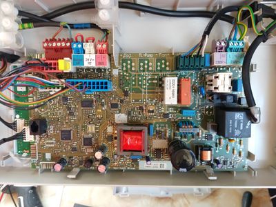
This is a description of how to replace the main PCB on the boiler.
The problem
A failure to heat or do anything really! So it has just turned really cold (-7.5°C apparently), heating was running just fine on Thursday night, but come Friday morning, it is feeling a bit nippy. I glanced at the main VR470 stat / programmer / weather compensation control in the hall, expecting it to tell me all was well, and just how cold it was outside. The first indication that all was not well: it was completely blank and non responsive.
Diagnosis
So checking the MCB for the heating circuit, then the fuse in the switched fused connection unit in the airing cupboard that feeds the heating system, showed those were fine. In fact turning off that supply resulted in the motorised valves springing back to their "un powered" state. So power was definitely good.
So dive a bit deeper; I took the cover off the boiler, flipped down the electronics enclosure and took the cover off that. Using a multimeter checked the fuse there was ok. Turning the power back on, and turning the boiler back on resulted in its LCD lighting up, and the boiler started its normal power on cycle. It ran for a few seconds, and then shut-down completely. No fault code, no diagnostic message, just "off".
Now that is pretty unusual for these boilers - they have loads of built in self test, and can report a wide range of diagnostic fault codes. However to do that, they need to be turned on, and apparently this one no longer was. Powering down, waiting a bit and turning on again would result in the same result. This was looking increasing like a control system problem - and most likely a fault in the power supply section of the main PCB. As a final test, I checked that the pump was not shorting its power feed, and while I was at it made sure its impeller was able to spin freely by turning its shaft with a screwdriver (having removed the access cap on the front).
So now it looks pretty likely it is a PCB fault. I did a visual inspection of it, nothing that had obviously let out the magic blue smoke (for those unaware modern electronics runs on magic blue smoke - if you let that out it stops working!). No water damage.
It is a ten year old PCB, so my next thought was failing electrolytic capacitors. There were not that many on the board, so I then tested those in-circuit using my ESR meter. Some were slightly below marked value - but still within 15% the intended spec - so not conclusively bad. While I had most of the values in stock as spares, I did not have anything I could replace the main 100uF 400V reservoir cap with. More to the point, it was cold and getting colder, so swapping the whole board seemed like a more expedient and certain way of fixing it ASAP than romping off down the component level repair option.
So I thought; "what I need is a man in a van with a nice stash of spares". Alas a quick phone round all the local fitters as recommended on the Vaillant web site made it quite clear that it was a very busy time of the year, and a visit in the next fortnight was not going to happen. A chat with one helpful fitter was handy though since he was also convinced from the description of the behaviour that it was a PCB fault.
Getting a replacement
So dreams of a same day fix have now well and truly having faded, it seemed easier to order in a recon PCB.
A quick chat with Geoff at the excellent CET Ltd, had one on order. At this point it was a case of find all the fan and other plug in heaters around the house, light the log fire, and switch on the immersion so it can do the hot water cylinder. No doubt we can hold out for a day!
This is where is started going a bit pear shaped. The next day delivery turned into next working day - so Monday. A packing error then delivered a PCB for a completely different boiler. Courier woes (something about abnormally cold weather and snow - yes tell me about it!) then extended the final delivery of the right bit by another several days! Brrrr.
I think on Wednesday it occurred to me that if this was capacitor failure, there is a quick and dirty hack that might help. Cold caps have a lower capacitance than warm ones, especially when on their last legs. If it was the main reservoir cap that was unable to deliver the power during a surge at startup, we might be able to coax some extra from it if we warm it up a bit. So I stuck the "non working" PCB back in, and set about warming the PCB with a hair drier. Then powered it back on - it started like before - but this time it carried on! Yay, warmth - it then ran all day pumping some heat back into the now thoroughly cold place. Had to do the same trick on Thursday morning, but fortunately the courier finally turned up with the missing board in the afternoon.
Swapping the board
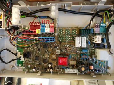
These are very straight forward to swap out. On this revision of the PCB, all the terminations are onto connectors that can be unpluged from the board - so no need to disconnect any wires from screw terminals. Some of the connectors are "edge" connectors. These just slide off the board. The multi pole connectors are polarised, colour coded, and have a side retaining clip you need to depress to free them from their sockets. The most difficult to free is the HT lead that runs from the HT transformer on the board to the spark igniter in the boiler. This is connected via an insulated spade terminal that has a fairly tight grip on the terminal on the transformer. This can be wiggled free with a fairly firm pull on the terminal.
The board itself is retained by three plastic clips built into the enclosure - push these out of the way, while gently lifting the lower edge of the board. It will come free. It can then be "unhooked" from the clips at the top.
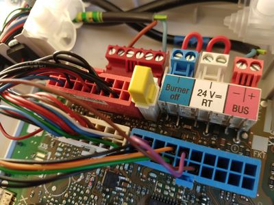
There is a small yellow "personality" module that is specific to the model of boiler, and it informs the PCB which boiler it is in, this also needs to be unplugged from the board and moved to the replacement.
The new board can be fitted in place and all the connectors plugged back in.
Powering on
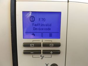
Now if the replacement board came from an identical model of boiler, that may be all that is needed. However chances are it will not have, and the control logic will spot a mismatch between the boiler's id module and the information held in the non volatile memory on the board. The boiler will power up, and display a "F.70 Fault invalid Device Code" message.
The PCB came with a Vaillant manual excerpt that listed all the models of boiler that are supported by the PCB (about 50 in total - scanned copy here). This was split into country specific sections (each country has a different model number prefix - so there were in total 15 pages of data to cover every model in every local).
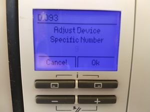
Mine was a VUW GB 246/5-5, and that needs a device code of "09".
So you now need to use the boiler front panel to go into "installer mode" (hold both "i" buttons together, and select from the menu. It will prompt for the "secret" installer code - normally 17).
You can go to the Device code menu. Here you can select one of a number of device codes to fiddle with (there are many of them - use the + and - buttons to scroll up or down through the list).
The boiler will give a brief description of what each code is for. Which ones are available will depend on model and type of boiler - but these let you configure a multitude of settings like the maximum flow temperature, or the pump speed, or the overrun time, how valves and external relays etc need to be controlled). Note if you have one of the posher controllers for the boiler, like one of the weather compensator models, many of these settings can also be altered using the more wordy controls available there.
For this job we need code "D.093 - Adjust Device Specific Number", select that, and set the number to the value taken from the model lookup table - (so 09 for my boiler).
Once that is done. normal operation resumes, tada! You just need to set the date and time. (fortunately the more elaborate configuration of my multiple heating zones and other parameters is retained by the weather compensator, and not the boiler).
You can now put all the covers back on, and wait for it to decide that the hot water cylinder really needs a refresh because the lady of the house just had a shower, and that is going to take priority over heat! (not helped because this also happens to be the day I had elected to have an "anti legionella" cycle where it heats the cylinder 10 degrees hotter than normal to make sure it is completely sanitised).
