Droppers
Droppers are electrical components used to reduce voltage to a load or appliance, and are used for various purposes in DIY, such as:
- Reduce fan power, speed and noise
- Reduce pump power, speed, pressure and noise
- Greatly extend life of filament lamps
- As fluorescent, mercury & sodium lighting ballasts
- Use in overcoming cable voltage drop with 12v halogen lamps
- Reduce power consumption of some appliances
- Running some 110v appliances off 240v mains
- Enable more appliances to be used on generators
How they work
A dropper is a resistance or reactance placed in series with the load. In use the dropper drops some of the supply voltage, leaving the load with less voltage.
One consequence of this is that if load current changes, so does load voltage. Thus droppers are primarily suited to loads with a constant current draw. Having said that, some loads with variable current also work with droppers, but far from all.
Droppers can also be used with a lot of switched loads, when the rise to full mains voltage doesn't matter when the load is not drawing current.
- Resistive droppers work happily with ac or dc.
- Capacitor and inductor droppers only work with ac.
- Triacs and transformers are also only used on ac (with some specialist exceptions that are far outside of household DIY)
- Diodes work on ac or dc, but with a different mode of action in each case
Ease of Use
Where droppers are used permanently, they are wired in place.
A convenient way to use of temporary droppers is to wire 2 mains sockets to a lead, with the sockets connected in series. Then any suitable plug-in device can be used as a dropper with any suitable appliance. This makes the use of droppered appliances effortless. Such leads are especially useful when using generators. Its best to label the lead to avoid wasted time with people thinking they have faulty appliances.
Safety
If you're unfamiliar with all the issues with droppers, it's recommended to have someone suitably skilled check your plans before you put them into use, as there are a number of gotchas with these things, and an ill designed dropper can destroy some equipment very quickly.
Droppers
There are 4 types of dropper:
- Resistance
- Inductor (choke)
- Capacitor
- Diode
The following are also used instead of droppers in some cases:
- Triac
- Transformer
- Diode
Resistor
These are not recommended as general purpose droppers, as they consume power and can produce considerable heat. Hence resistor droppers are usually used for micropower applications, such as driving LEDs from low voltage.
Chokes & Capacitors are preferred for most applications as they dissipate very little heat, ie don't waste significant energy.
The power dissipated in the resistor equals the voltage drop across it multiplied by the current through it. The resistor chosen must be rated to handle at least this much power. The mounting of resistors dissipating more than a fraction of a watt needs to be considered, as they can run very hot.
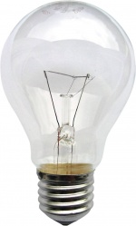
Lightbulb
Filament lightbulbs make convenient temporary droppers for some jobs. They are resistive, but their resistance varies with filament temperature. Cold resistance is around 1/8th the resistance at full power. This makes lightbulb dropper calculations always approximate. It also results in a brief moment of nearly full voltage to the load at power-on. Some loads seriously object to this.
High power 110v halogen lamps are useful as temporary droppers to enable power tools, kettles etc to run on small portable generators.
40w, 60w and 100w household light bulbs can be used to control small heaters, such as used for brewing, propagators, aquaria etc. These are fine for short term use, but unnecessary power consumption means capacitors are better droppers for long term use.
2 filament lightbulbs wired in series are occasionally seen as a means to obtain extremely long lamp life. While successful in this respect, the resulting energy efficiency is dire, and the money thus wasted becomes excessive over time.
Choke
Small chokes (aka inductors or coils) have low reactance, thus chokes are often used where small amounts of dropping are required.
Chokes produce a momentary high voltage inductive kickback when current flow is switched off. This can be high enough in voltage and current to destroy insulation and fry humans, so a means of absorbing it should be provided. Failure to do so invites equipment breakdown, and is sometimes unsafe.
Chokes do produce a little heat, and some can get quite hot in use. PVC wiring should be routed so it can't come into contact with the case of a hot choke.
Chokes have a current rating which must be observed. Exceeding this results in
- rapid drop in reactance, increasing power to the load,
- choke overheating & failure
- occasionally fire
Chokes can be connected in series to add their inductance up to the required value, but its rarely useful to do so.
Capacitor
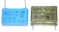
Capacitors have some advantages over chokes, but small low cost capacitors have high reactance. Hence these are primarily used where their relatively high reactance is usable, ie as droppers for low power loads.
No significant parasitic resistance means capacitors run cold and waste no power.
Capacitors don't produce inductive kickback. However they do store charge when switched off, in some cases enough to bite a person fairly hard, so a bleeder resistor should be fitted across the capacitor to discharge it.
Capacitors should also not be shorted, as doing so will burn out the switch used prematurely. Attention should be paid to this when designing switchable speed controls.
Voltage Ratings
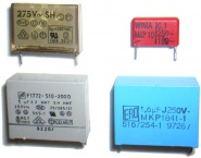
All capacitors have a voltage rating, but the situation is a bit more complex than it first appears. These ratings are sometimes misunderstood, and for example a capacitor marked just '250v' is entirely unsuitable for mains use.
There is more than one type of capacitor voltage rating in use:
DC ratings: most capacitors use this method. Here the dc voltage rating is marked on the case, eg as 400v. For most mains use, 600v rating is required (400v is sufficient on filtered mains, but this does not apply to most DIY uses).
AC ratings: The capacitor is marked as so many V ac, eg 250vac. 250vac capacitors are not necessarily suitable for use on unfiltered mains, as mains carries transients which will exceed this by a large margin and are liable to destroy the capacitor.
2 of the caps in the picture above are suitable for mains dropper use, 2 aren't. Check you know which is which.
Class X & Y Capacitors
Class X capacitors should be used for L-N applications, or where the voltage drop is a large percentage of mains voltage. Class X caps include an additional safety feature over more basic types.
Class Y capacitors should always be used in any situation where capacitor breakdown could expose mains voltage to touch, or pass current to anything earthed. Class Y caps are both self-healing and fusible, more safety features than Class X types.
Class X and Y capacitors usually have ac voltage ratings and have mechanisms for surviving transients, thus a 250v ac class X capacitor can be used on mains.
Parallel Capacitors
Capacitors can be parallelled to add their capacity up to the required value.
Connecting capacitors in series to increase voltage ratings is possible in principle, but brings complexity. The total voltage rating then depends on leakage currents, relative capacitance values and tolerances, and errors may result in failure or fire. So this is not something to do unless you understand and address all the resulting issues.
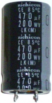
Electrolytic capacitors
Electrolytic capacitors are not suitable for use as droppers.
Transients & Switching
Capacitors have a certain reactance at 50Hz, but with much higher frequencies they only have a fraction of the reactance. Consequently
- when initially switched on, in their first 100th of a second they tend to pass much higher current.
- Mains transients will also cause higher current spikes with a capacitor dropper.
This is not a problem for loads designed to run on 240v, nor in most cases for loads designed for 110v. However it can be a big problem in some cases. Where it is, either an inductor or a CR dropper is used instead.
Capacitor & Resistor
CR droppers are used where a capacitor dropper is wanted, but the switch-on current surge created by capacitor dropping is problematic.
o-------/\/\/\------||--------o

          R1        C1
The resistor usually only does a small percentage of the dropping, but during switch on and with mains transients the resistor limits current and drops more.
Mains LED bulbs use CR droppers.
CR droppers don't generally survive operation on MSW invertors. These cause greatly increased dissipation in the resistor, and failure or occasionally fire.
Example CR Design
How to design a suitable RC power supply for an indicator LED to run on 240v mains.
First you size the C for the wanted i. 2mA would require 120kΩ, which at 50Hz is 0.0266μF. 0.022μF is the NPV. Modern LEDs don't need more current for indicator use.
Then you size your R for the peak current under any circumstances. If we allow 0.33A at a peak of 330v we need 1kΩ.
Next: capacitor ratings. A mains capacitor requires a 250v ac X2 rating. 400v & 600v caps were formerly used but fail too often on mains, and lack safety features.
Now resistor ratings. 1kΩ at 2mA rms drops 2v rms & dissipates 4mW, so power rating is no issue. A 400v rating is a minimum, and typical through hole parts are rated to 200v, so 2x 470 ohm in series will do the job.
Finally the diode that goes back to back across the LED. It must cope with 0.33A peak and a few volts in reverse - not a demanding spec, but germaniums & some small signal diodes are unsuitable.
Capacitor & choke
Capacitor plus choke produces major issues not seen with other dropper types. It rarely makes a suitable or safe dropper. The only commercial application of such droppers that I'm aware of is in obsolete fluorescent ballasts. Don't try this combination.
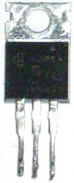
Triac
Triacs reduce load power consumption by switching the power typically 100 times per second, rather than by dropping voltage across the triac. Parasitic power loss is small, the triac is electronically controllable and the power throughput variable, and unlike L, C and R, the effect a triac has on the load does not vary according to load current. This makes triacs popular for some uses such as dimmers & universal fan speed controllers.
Triacs are pulse width modulating controllers rather than impedance droppers. The effect on some appliances is much the same, and on some appliances different.
Triacs work with loads that don't care about wave shape or peak voltage - which excludes a lot of loads. A triac on its own is of no use, an electronic circuit is needed to drive it. Lighting dimmers and universal fan speed controllers are readily available triac controllers.
Triac controllers should not be used with inductive loads unless the controller is designed for them. Fan controllers are intended for inductive loads, lighting dimmers aren't. Where lighting dimmers are used on resistive loads with slight inductance, such as soldering irons, putting a snubber across the load can absorb any small inductive spikes that could otherwise cause damage.
Triac controllers should not be used with transformers.
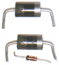
Diode
Diodes behave differently on a.c. and d.c..
Diodes on a.c.
Diodes are occasionally used as mains droppers. Like the triac, they chop the mains waveform rather than drop its voltage, but diodes give a fixed 50% chop, conducting every other half cycle of power.
When used as mains droppers, diodes must be rated to the highest peak voltage they will ever see. 400v rating is inadequate, 1kV is recommended. This may be reduced to 600v if a snubber is permanently connected across the diode, and the load is primarily resistive.
Diodes also have to be rated to the highest peak current they will ever see. This can be far above mean run current. For example for filament lamps a diode would need to be rated to 14x rms run current to be stay within spec and be long term reliable.
Diode droppers must not be used in conjunction with transformers, either before them or after them. They are also unsuitable for use with inductive loads.
Diodes are used with filament lamps in the US to achieve long lamp life. This is unworkable in the UK, our thinner 240v filaments would produce heavy flicker.
Diodes on d.c.
Diodes are sometimes useful for small drops to low dc voltages, such as to use a wallwart with a lower voltage appliance.
On dc, diodes typically drop around 1v each. (It is often said that silicon diodes drop 0.6v, but this is the voltage at which they begin to conduct, not the typical V_drop with greater current flow.)
Where finer tuning of voltage is needed:
- silicon diode V drop varies from one type to another at any given current,
- Schottky diodes drop much less voltage than standard silicon diodes.
- A resistor can be included to drop a fraction of a volt
Diodes have the advantage over resistors of much less change in V_drop with current changes. Diode droppers on regulated supplies work quite well, introducing a little deregulation.
Diode droppers with unregulated wallwarts
However diode droppers on unregulated supplies, especially small wallwarts, can result in supplies with gross deregulation. An example will show why.
We will take a 12v unregulated wallwart, and drop this to 5v.
Used as a 12v supply, a wart may produce:
- 12v at full load
- 16v at low load
To get 5v at full load with diodes that drop 1v each, we use 7 diodes. This then gives us:
- 5v at full load (12v - 7x 1v)
- 11.8v at very low load current (16v - 7x 0.6v)
This much deregulation is something few appliances will tolerate. Thus diode droppers are best used on regulated supplies, or with appliances that consume a steady current or don't mind wide swings in voltage.
Appliances that can't tolerate such conditions can use a voltage regulator instead. However these require basic electronic circuit assembly, which is outside the skill set of a lot of DIYers.
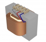
Transformer
Transformers are not impedance droppers, but are sometimes used for the same job. The 2 are different, but there is significant overlap in their uses.
Transformers may be used to :
- reduce filament lamp voltage
- increase filament lamp voltage to improve energy efficiency
- reduce power consumption of low power heaters, such as propagators, yogurt makers, brewing heaters etc
- Run 110v appliances
- Run some mains appliances on reduced voltage to enable their use on small generators
Unlike L, C and R, transformers produce a relatively steady output voltage despite changes in load, hence they're used where the potential variations of impedance droppers are unacceptable.
Be aware that 110v site transformers are typically not rated to provide full power continuously. Continuous use requires derating to prevent failure.
Transformer Connection
Small Voltage Drop
      ______________
 ____|____      ____|
L         ) || (
          ) || (
     240v ) || ( 18v
          ) || (
          ) || (
M_________) || (___________  220v
     |                        to
     |_____________________  Load

Use of transformer to drop a small voltage
With the secondary winding connected one way round, the transformer drops V_out. With it connected the other way, it boosts V_out. Check with a meter to see if you have boosted or dropped output before connecting the load.
Note that this connection does not give isolation, the output is connected to the mains and still live. This configuration also does not block RCD protection of the downstream appliance.
The required transformer VA rating is its secondary voltage multiplied by the load current. Thus a small transformer can run a much higher power load.
Transformers don't care about brief overloads, as their limiting factor is temperature, and large lumps of metal take time to heat up. Consequently some transformers are thermally protected but unfused. This enables them to supply well above rated power for brief periods. So starting surges of motors and so on can be ignored when selecting transformer power rating.
Finally, the voltage rating of transformer secondary windings is a little different to the voltage actually seen in this circuit application. In practice the secondary voltage seen will be a bit higher than the transformer spec. This is due to transformer regulation, which won't be covered here. This extra voltage drop equals
- at full rated load, twice the transformer regulation
- at no load, 1x transformer regulation
So an 18v 10% regulation transformer used as above actually drops 19.8v no load, and 21.6v at full load.
Large Voltage Drop
When a transformer is used to drop a large proportion of the supply voltage, the following configuration is used:
 _________      ___________
L         ) || (
          ) || (
     240v ) || (              To
          ) || (             Load
          ) || (
N_________) || (___________

Use of transformer to drop a large voltage
This configuration gives isolation. Low voltage outputs can be touched without harm. (This assumes a standard equipment transformer is used. There are also non-isolating transformers in existence, but they're not common.)
Isolation also means any upstream RCD protection will be ineffective after the transformer. If an appliance needs RCD protection as well as isolation, which is occasionally necessary, an RCD would need to be connected after the transformer to cover the appliance.
This configuration is also sometimes used for small voltage drops. But there is no power ratio advantage as there is with the previous configuration, a 100w load requires a 100w transformer.
Variacs
Variacs are variable transformers. Output voltage is controlled by a large dial, and can be adjusted over the full mains voltage range, and usually a little beyond.
Variacs have a habit of giving people electric shocks, not because there's anything wrong with them, but people new to variacs sometimes don't realise that unlike most transformers, they give no isolation, thus the output is always live, even when output voltage is set low.
Variacs are the most versatile power controllers of all, as their behaviour toward the load/appliance is excellent in almost all respects, which can not be said of most methods of reducing voltage, plus they're fully variable. However they're expensive and bulky compared to all other voltage reducers, so are little used today.
Most variacs in existence are historic, pre-dating low cost triac controllers. When buying a used variac some basic safety checking is wise, they often aren't wired up safely. Bare live terminals etc may be encountered.
Applications
- Fan Speed Controller: switched capacitors in modern equipment, inductor or tapped inductor in older equipment. Other methods are also in use such as tapped motors and triac controllers.
- Universal fan speed controller: triac
- 12v Halogen lamp voltage adjustment: inductor,
- Heater power reduction: inductors & sometimes lightbulbs or another heater
- Small heater power reduction: inductor, capacitor, diode, lightbulb, triac, transformer, variac.
- LEDs: resistors for low voltage, resistor + capacitor for mains use, transformer for mains & use on invertors.
- Temporary droppers: light bulbs & plug-in heaters
- Computer fan quietening: resistor, or less often diodes
Reducing power consumption
Reducing power consumption of some devices can be useful for:
- non-thermostatic heaters
- Increasing the loads that can be run off a portable generator.
- Eg a kettle fed via a dropper can allow a nice hot brew without stalling the gen, and while still using power tools.
- Eg a power tool too powerful to run on a small gen can be operated via a dropper to enable its use. Note this affects performance of some tools badly.
- limiting aquarium heater fault power to prevent fatal overheating in case of thermostat failure.
How its done:
- Inductors or capacitors are usually used.
- Series light bulbs can sometimes be used as a temporary measure.
- Dimmers may be used for small heating loads below the dimmer's max rated load (typically 250w-500w), eg propagators, brewing heaters, fish tank heaters, soldering irons, etc
- For generators, connecting 240v loads to 110v is another way to reduce power consumption. Sometimes this is simpler.
110v appliances
These are normally run off transformers in the UK. However in some cases a dropper will do the job with the advantages of low cost, small size, light weight and no power loss. Appliances with non-varying loads can usually be run happily off a dropper. Appliances with widely varying loads, eg drills, will not behave well with droppers, and any 110v electronics, such as the speed control circuitry in drills, is likely to die quickly if run from 240v via an impedance type dropper.
Suitable for droppers:
- 110v non-electronic lighting (filament, halogen, iron ballasted fluorescent)
- ammonia absorption cycle fridges (not compressor types)
- resistive non-electronic loads such as slow cookers, soldering irons
- single speed fans & pumps
Unsuitable for droppers:
- Anything containing electronics
- Fridges & freezers with a compressor - droppers block the high startup current these need, causing repeated stalling.
- wallwarts
- Any US appliance with the case connected to the mains, either directly or via a capacitor. A small amount of such (historic) equipment is still out there in the US.
Motor repairs
Droppers are sometimes used to limit current on motors drawing excessive current, to enable them to continue in service safely and effectively long term. This is without doubt a bodge, but since it meets the essential requirements of working acceptably, being safe and being reliable, its sometimes a fair option. Its occasionally used to repair domestic appliances where motor rewind or replacement is uneconomic. It sees more use in industrial situations where motor replacement or rebuild is a more expensive option, and down time costly.
For more information see Motor repairs
Maths
Resistance and reactance don't add, mathematically they behave 2 dimensionally. The resulting maths isn't tough, but its also not trivial.
Formulae
Voltage = Current x Resistance
Voltage = Current x Reactance
Dropper reactance (ohms) = Dropper voltage (volts) / Dropper current (amps)
For capacitors:
- C= 1/(2 x pi x frequency x reactance)
where:
- pi = 3.141,
- frequency = 50Hz for UK mains
- Reactance is in ohms and C in farads
- Capacitance C in the above formula is in Farads
- Dropper capacitors are normally sized in microfarads. uF and mfd both mean microfarads.
For inductors:
- Inductance = 2 x pi x frequency x Reactance
where:
- pi = 3.141,
- frequency = 50Hz for UK mains
- Inductance is measured in henries or millihenries
- Reactance is in ohms
- Inductance is in Henries
For motors:
- Reactance^2 + Resistance^2 = total impedance^2
- Impedance^2 = Voltage^2 / Current^2
- Voltage x Current = VA (not power in watts)
- VA is always significantly higher than Power for motors.
Cable voltage drop can normally be ignored as insignificant for 240v applications, but is usually important in low voltage circuits, especially high current ones like halogen lighting and pumps.
Vector Diagrams
For each situation, things can be sketched out by plotting resistance on one axis and reactance on the other, with inductive reactance and capacitive reactance in opposite directions (eg +x and -x). Diagrams are given for the usual combinations, which hopefully will help clarify things, and can be used as a double check.
There are 2 types of loads suitable for droppers:
- Resistive - has resistance only
- Inductive - has resistance and reactance. This description applies mostly to motors, and some other wound loads such as nonelectronic fluorescent lights.
Note that inductive droppers have a little resistance as well as reactance.
Resistive Load & Resistive Dropper
This combination is uncommon, but would describe light bulb droppers running a small heater, or possibly a kettle on a portable generator.
In this case there is no significant inductance in the circuit, and the equation is simple and 1 dimensional.
  _______.___________
  Load R   Dropper R
  _______.___________
  Load V   Dropper V
In other words:
- Total R = Load R + Dropper R
- Supply V = Load V + Dropper V
Resistive Load with L or C Dropper
This applies to either L or C dropper with a resistive load (eg heating element or light bulb), The various voltages in such a dropper circuit are related as follows:
         Cable  |\
        v_drop  | \
               _|_ \
                |   \
         Load   |    \   Supply
        voltage |     \  voltage
                |      \
                |       \
               _|_       \
Dropper R vdrop |_________\
 (for L only)   Dropper L or C
                voltage drop
So if we ignore cable v_drop and inductor resistance, (Dropper voltage)^2 + (Load voltage)^2 = (Supply voltage)^2
Choke Dropper & Motor
The voltages in a choke dropper motor circuit are as follows:
              |\
              |  \
              |    \
       Motor  |      \
         L    |        \    Supply
       V_drop |          \   voltage
             _|_           \
              |              \
      Dropper |                \
     L v_drop |                  \
              |______|______|______\
              Motor R  Cable  Dropper
              v_drop   v_drop R v_drop
Note that here the motor voltage is divided into 2 portions, the drop due to its inductance and the drop due to its resistance. These are related as follows for a 240v motor:
         |\
         | \
         |  \   Motor
  Motor  |   \  terminal
    L    |    \  voltage
  V_drop |     \  (eg 240v)
         |      \
         |       \
         |________\
          Motor R
          v_drop
A motor's resistance can be measured directly with a multimeter. Knowing its current or VA rating its then possible to work out the other parameters.
How a motor behaves on reduced voltage depends on the motor type and the characteristics of the load. Most motors give reduced speed and power, but
- synchronous motors will usually maintain speed, or if V is reduced enough, stall.
- compressors can overheat
- fan cooled equipment can overheat badly if the fan stalls.
Capacitor Dropper & Motor
              |\
              | \
              |  \
              |   \
              |    \
     Dropper  |     \
        C     |      \    Supply
      V_drop  |       \   voltage
              |        \
    * minus * |         \
              |          \
      Motor   |           \
        L     |            \
      v_drop  |             \
              |_______|______\
              Motor R   Cable
              v_drop    v_drop
As you may notice from this diagram, it is possible for the total inductive reactance in the circuit to be _decreased_ by adding a capacitor in series with a motor, resulting in an increase in motor current flow. So when capacitors are used to control inductive loads, their value should be calculated correctly to prevent this, and avoid overpowering and toasting the motor.
A possible alternative to calculation is to put a multimeter across the motor and only power the motor up for a few seconds. If the motor voltage exceeds 240v, all is not well and the capacitor value is not suitable. This should not be done with large motors, as these can pull excessive currents in these circumstances.
Note that with motors, dropper capacitors can sometimes see more than 240v, and should be voltage rated acordingly.
When testing with motors, the motor should be driving its normal mechanical load. Without the load, its electrical characteristics will differ.
Capacitor Dropper with Resistive Load
       Cable  |\
      v_drop  | \
             _|_ \
              |   \
       Load   |    \   Supply
      voltage |     \  voltage
              |      \
              |       \
              |        \
              |_________\
                Dropper
                voltage
Glossary
- Resistance
- Reactance
- Inductance
- Capacitance
- Impedance
