Raspberry Pi repair
If you have ever wondered how well a raspberry pi can fly, then the answer "not that well". In fact it is not so much flight, as more a kind of plummet!
Setting the scene...
So a customer asked, what was the best way to run a video loop in the front window of their high street office. They already had a couple of old but fairly high end 32" professional display screens mounted in the window, but with nothing currently hooked up to drive them. In the past they had been driven from a PC via a pair of long VGA leads and a VGA splitter. But following an office refurb, that had gone. So I suggested a Raspberry pi was normally a fairly cheap and discrete way of doing it, and while the screens were not new enough to support HDMI, they did have a DVI port on the back which with the right lead could do the job.
So a plan was formed, I would set up a pair of pis, that could be discretely mounted on the back of the TVs. On power up, they would mount a folder from their network fileserver, and play any videos found there in a never ending loop.
So after installing the first one, and getting power and network connections to it without all looking too unsightly, we discovered that the customer no longer had the remote controls for the screens, and there appeared to be no way to select the DVI input from the limited button controls on the screen. Which was a bit of a show stopper. However the customer did mention that he had managed to drive one from his laptop using the remains of the VGA connection still attached to the screens, and the end of those were tucked behind a panel near the floor at the front of the office. So out of curiosity I tried hooking a pi up to that via a HDMI to VGA adaptor, and tada! It worked (aspect ratio was a bit wonky, but that could be fixed in software). So set about de-installing from the back of the monitor mount. It was during this process that butterfingers managed to nudge if off the screen while only attached via the USB power lead. It promptly pulled free from that, and started its trajectory to the ground. Now to be fair, the free fall section of its day trip left it unscathed. The brutal landing, on a hard floor, did it few favours. To make matters worse, this was an original Pi Model B, with the full sized SD card sticking out one end of the case, and that is what it landed on.
The damage
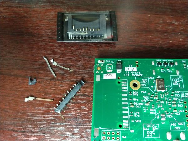
Most of the SD card slot was snapped off, but the base of it remained at a somewhat jaunty angle still soldered to the board. Given Pis are in short supply at the moment, it seemed prudent to fix it rather than scrap it. A bit of research suggested that the original socket was made by Valcon with a part number of 412D, and these can be ordered from Toby Electronics
The Fix
First job was to get the remains of the broken connector off. Since its pins were pretty close to some very fine pitch surface mount resistors, I decided against using the hot air station, as the chances of finding one of those if I blew it off the board were slim! So I applied some flux and worked over each of the joints with some "Chip Quik" low melting point Bismuth alloy solder. This mixes with the lead free solder on the joint, and allows it to be melted at a much lower temperature. It also moves the solder well away from its eutectic point, allowing a much wider temperature range between its fully solid and fully liquid states. This makes it easy to get all the pins on multi leg devices melted at the same time, and it slid off the board.
Once all the broken bits of socket were out of the way, I could clean up the pads with some flux and de-soldering braid, and see what state the board was in.
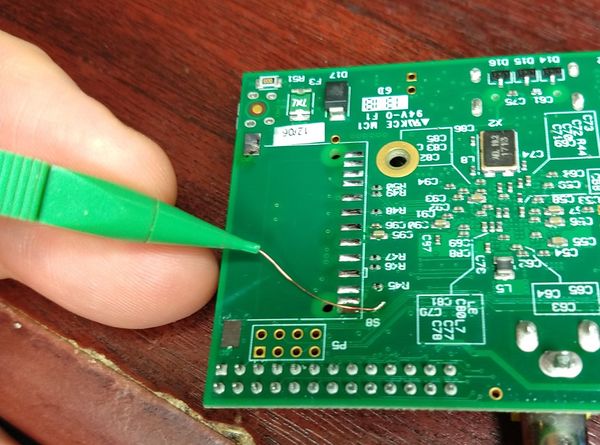
It was mostly ok. However two pads had been ripped off the board by the impact. One was just a mechanical fixing point at the outer edge of the socket. That did not matter. However there was also a pad missing on the first pin of the socket. Looking closely at the pad, there was a very small PCB track visible that ran for a few mm before it went to a via not far from the pad.
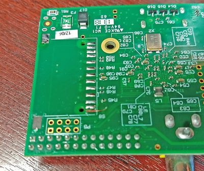
So I scraped away the solder mask over it trace to expose some copper. Then with the temperature turned down to 295 °C on my soldering iron, carefully tacked into place the free end of a bit of verowire with proper full fat leaded solder. While I was at it, I also fluxed and tinned up all the other pads.
Next I trimmed off the wire at the length of the pad, and scraped away its polyurethane insulation at the pad end. The new socket could then be dropped in place (it has a couple of registration lugs that engage with holes in the PCB).
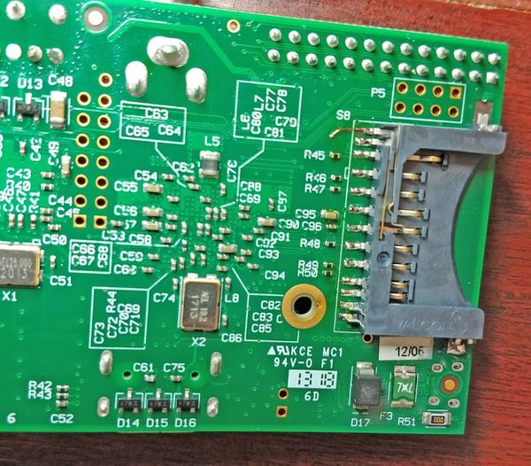
After adding a bit more flux, I could touch each pin with the tip of the iron with a small amount of solder already applied to it. That was enough to make each joint with the pad (or the vero wire in the case of the missing pad).
After each joint was inspected, I buzzed out the repaired pad connection with the multimeter, and that beeped nicely!
Final job was to clean up the flux, and apply some CA glue to the edge of the socket where the mechanical fixing pad was no longer available.
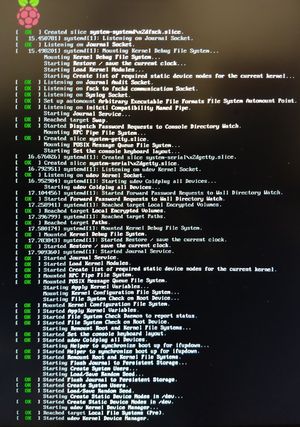
Final moment of truth, does it boot?
Nice one.
