Difference between revisions of "Lawnflite 703 Autodrive CVT belt and bearing replacement"
(WIP) |
(First release) |
||
| Line 2: | Line 2: | ||
=== Noisy === | === Noisy === | ||
| − | This time I noticed that the mower was making more noise than normal. Usually having the blades running make it quite a bit louder, but this was louder just driving about, even without cutting. However, I managed another cut'n'drop, which took a few hours, and then finally set about the sweep up the mess phase. Here the plan unravelled, as having got no further than 5m into | + | This time I noticed that the mower was making more noise than normal. Usually having the blades running make it quite a bit louder, but this was louder just driving about, even without cutting. However, I managed another cut'n'drop, which took a few hours, and then finally set about the sweep up the mess phase. Here the plan unravelled, as having got no further than 5m into the sweeping, the mower simply stopped. No drive forward or backward, and the accelerator peddle was flapping about in the breeze and no longer springing up when released. The obvious suspect was a broken drive belt, as I had noticed that after 16 years or so, they were looking like they [[:File:Lawnflite703IdlerWheels.jpg|were on their last legs]]. Spares had already been ordered and were ready waiting. Alas the enthusiasm to start fixing it on Sunday evening was not there, so at that point I pushed it off the lawn and waited for a flash of enthusiasm to go and investigate later. |
== Diagnosis == | == Diagnosis == | ||
| − | Surprisingly the knackered belts were still hanging on. The first obvious "fault" however was a vee belt pulley, that really looked like it should be attached to something was in fact laying in the bottom of the mower transmission. There is a bearing housing bolted to the frame of the mower that looked like it should be holding the shaft sticking out of the top of the pulley | + | Surprisingly the knackered belts were still hanging on. The first obvious "fault" however was a vee belt pulley, that really looked like it should be attached to something was in fact laying in the bottom of the mower transmission. There is a bearing housing bolted to the frame of the mower that looked like it should be holding the shaft sticking out of the top of the pulley, and In fact the retaining screw was still resting on top of the bearing housing. Checking that showed that the bolt was not broken, and the threads on both shaft and bolt looked good - it had just come undone for some reason. Checking the bearing, if felt rather rough. Unbolting the bearing housing revealed two 6203-2RSR C3 bearings (40mm OD, 17mm ID, 12mm thickness). The bottom one was "ok ish" but felt rough and had some slop in it. The top one was another storey though. The seals had come off it, the ball race metalwork had broken up, and a few of the balls had made a getaway, and it was seized! That kind of explains the extra noise. It also looked a bit discoloured from heat. The vibration had probably shaken the retaining bolt free. New bearings were ordered from bearingboys.co.uk. |
== Fixing it == | == Fixing it == | ||
| − | Since there were new belts waiting, it made sense to replace those at the same time as the bearings. Not a particularly difficult job, but a bit of a pain all the same. | + | Since there were new belts waiting (part numbers MTD 754-0626 (BB-66315) and MTD 754-0629 (BB-66316) - compatible parts made by the same OEM (PIX) that appear to make MTD's belts - also from bearing boys for significantly less money than those from a MTD / Lawnflite dealer), it made sense to replace those at the same time as the bearings. Not a particularly difficult job, but a bit of a pain all the same. |
| − | + | Most of the guides I could find online and on youtube seemed to cater for different models with different transmission layouts. Hence this guide in case anyone else finds themselves in the same situation. | |
| − | + | ===Disassembly=== | |
| − | + | (Click the pictures for larger versions) | |
| − | + | ||
| − | + | First job is to remove the grass collector, and remove the fixings from the bottom of the grass collector chute. | |
| − | + | [[File:Lf703_RemoveGrassCollector.jpg|alt=|none|thumb|600x600px|Might have been a good idea to empty *all* off the grass out of it!]] | |
| − | + | ||
| − | + | ||
| − | + | Now the chute can be withdrawn from the mower: | |
| − | + | [[File:Lf703_RemoveGrassChute.jpg|alt=|none|thumb|600x600px|This may be held in with studs and cotter pins, or more likely if they have been lost - a small bolt and nut]] | |
| − | + | ||
| − | + | ||
| − | + | Now the cutting deck can be removed. Drop the cut height selector to the lowest level - this will take the tension off the hangers that support the back of the deck. Pull on the spring loaded release bolt toward you to allow the hanger to pull free of the deck. Return the cut height leaver to the highest position to lift the carrier drop arms back out of the way. | |
| − | + | [[File:Lf703_PullDeckLiftLinks.jpg|alt=|none|thumb|600x600px|The cutting deck is heavy and a bit tricky to detach and refit. A strong pull on the looped end of the spring bolts will free them from the brackets. ]] | |
| − | *[[ | + | |
| − | *[[ | + | Now set about freeing the front of the deck. The deck will now slide forward a bit, and the bottom fo the front handing bars will move in the elongated slots, allowing them to be lifted clear of the deck. The deck drive belt can also be removed from round the big "power take of" pulley |
| − | + | [[File:Lf703_DisconnectDecBeltAndFrontCarrier.jpg|alt=|none|thumb|600x600px|You can see the L bracket here that will "catch" the pulley assembly and stop it coming right off the motor shaft. ]] | |
| + | |||
| + | |||
| + | Slide the deck out, and set it aside, we don't need this for now: | ||
| + | [[File:Lf703_SetDeckAside.jpg|alt=|none|thumb|600x600px]] | ||
| + | |||
| + | |||
| + | Access to the rear section of the mower where the rear axel and drive system is located, is rather limited. Some of it can be seen through the rear grass exit port, but for better access can be found under the battery. | ||
| + | |||
| + | So, disconnect the leads from the battery (-ve first to save any nasty shorts with your spanner, since all the metalwork on the mower is connected to the -ve). Remove the battery and its rubber retaining strap from the battery tray, and lift out the battery. Once the battery is out, the battery tray will also lift out revealing access to the mechanicals below: | ||
| + | [[File:Lf703_DisconnectAndRemoveBattery.jpg|alt=|none|thumb|600x600px|Lift the mower seat to get to the battery]] | ||
| + | |||
| + | ===Replacing the pulley bearings=== | ||
| + | The next stage was to fix the bearing. To do this unbolt the three bolts that hold the bearing carrier onto the mower frame. This can be done via the battery access hole. The bearings are a snug but not particularly tight fit and can be pushed out with your thumbs.The hosing then cleaned up, and any dirt, rust, and bits of failed bearing removed! | ||
| + | |||
| + | The new bearings can be pushed back into the housing, and it bolted back in place. The pulley shaft can now be taped back into the bearings, and the retaining bolt and washer re-fitted to hold the pulley in place. | ||
| + | [[File:Lf703_BearingHousing.jpg|alt=|none|thumb|600x600px|The CVT shaft bearing holder]] | ||
| + | |||
| + | |||
| + | For the next stage, easy access to the underside of the mower is required. Rather than try to work under it, I elected to tip it onto its side (this is not too difficult once the cutting deck removed since this is a heavy part with a low centre of gravity). A strategically placed roll of offcut carpet was placed to give it a soft landing. | ||
| + | |||
| + | When tipping it, tip it onto its right hand side - this keeps the carb uppermost and stops it flooding. Also do it when the petrol tank is close to empty. | ||
| + | |||
| + | We can now see the layout of the drive system. | ||
| + | |||
| + | ===The drive system - how it works=== | ||
| + | These mowers have a belt driven Continuously Variable Transmission (CVT). There is no conventional gearbox and there are no changeable gears. The engine speed is set by the throttle leaver next to the steering wheel, the direction is set by the Forward - Neutral - Reverse selector to the left of the rider (the changes being implemented in the diff), and the movement is all controlled from a single "go" pedal. The further you push the peddle, the faster the mower goes - all without altering the engine speed. | ||
| + | |||
| + | Anyone who has studied the drive system of old "Variomatic" DAF cars (later acquired by Volvo) might have an idea how this is accomplished. | ||
| + | |||
| + | The first (longer) drive belt it looped round a small pulley on the output shaft of the motor. It then passed to an intermediate dual vee pulley toward the back of the mower. The belt in its rest state is fairly slack, but it also passes through a pair of idler wheels in the middle. One of these is fixed in position, but the second can be rotated through a 45 degree arc by pushing the go pedal. This has the effect of lengthening the path of the drive belt, pulling it more tightly onto the pulleys. | ||
| + | |||
| + | This achieves two things: it provides a clutch action for the drive - with the belt slack, the motor power is not delivered to the drive and the engine can "idle" without the mower moving even if left in forward or reverse. The second is to control the effective gearing. | ||
| + | [[File:Lf703_LongDriveBelt.jpg|alt=|none|thumb|600x600px|The overall layout and route of the front drive belt and the rear CVT pulley]] | ||
| + | |||
| + | |||
| + | The gearing is controlled by the "magic" double vee pulley. This has a pair of deep vee pulley slots in in. The top and bottom vee profiles are fixed, however the centre section with two vee sides is free to slide up and down on a short shaft between the top and bottom pulley faces. | ||
| + | |||
| + | The power input belt is looped round the top pulley, and output belt that goes to the rear differential, loops round the bottom section. The output belt has a spring loaded tensioner on it. So in the "rest" state the lower belt pulls more tightly into its pulley. This forces the free centre pulley section to slide up. That means that the top input belt is forced into a large circumference route round the pulley, and output shaft gets a much smaller circumference path. | ||
| + | |||
| + | As the rider pushes the go pedal, it tightens the input belt. First this engages drive - with a low effective gearing - the large input pulley circumference and small output pulley circumstance giving a higher mechanical advantage. However as the pedal is depressed further, the force exerted on the pulley by the input belt starts to exceed that of the spring tensioner on the output belt. This forces the floating pulley section downwards. Reducing the input belt circumference, and increasing the output belt circumference - giving the effect of a "higher" gearing. With the go pedal fully depressed, the input belt will be pulled deep into the top grove and the output belt forced right out to its maximum circumference - giving the highest gearing possible and the most travel speed. | ||
| + | |||
| + | If the load on the mower increases (say from towing a heavy trailer), this will increase the drag on the output belt, increasing the effective tension on it, and it will "push back" against the floating pulley, causing the gearing to lower slightly - reducing speed, but increasing torque - automatically compensating for the load. | ||
| + | [[File:Lf703 CVTMagic.jpg|none|thumb|768x768px|The CVT pulley with the middle sliding section. Seen here with no pressure on the go pedal. The bottom belt from the diff is pulled tight into its vee groove by the spring tension it the belt. The sliding section it in its highest position, and the input belt is forced round the larger radius.]] | ||
| + | |||
| + | === Changing the front drive belt === | ||
| + | |||
| + | |||
| + | The first belt to tackle is the longer "input" belt. This passes round the smaller pulley on the motor output shaft. It has a number of metal fingers that are placed close to it which prevent it from falling out of position on the shaft when the belt is slack. However this also means that it is not possible to remove of fit a belt with the pulley in this position. | ||
| + | [[File:Lf703_CaptiveDriveBelt.jpg|alt=|none|thumb|600x600px|Close up of the motor output pulley. This one always spins at motor speed. Note the fingers that trap the belt on the pulley. ]] | ||
| + | |||
| + | |||
| + | To free the belt it is necessary to move the pulley away from the motor a bit so that it can clear the metal retaining fingers. To do this you will first need to remove the smaller of the two bolts on the bottom of the big PTO pulley (place a large spanner on the big nut and hold it steady, and undo the smaller bolt head). | ||
| + | |||
| + | You can remove the bolt completely, and the whole pulley and PTO clutch and pulley will slide down the motor output shaft. However there is a metal L bracket that will prevent the pulley coming right off the shaft. This will allow space for the old belt to be removed and the new one placed onto the motor pulley. | ||
| + | |||
| + | However there is one more obstacle - the spring loaded linkage that connects to the PTO control leaver from the blade engage leaver to the left of the steering wheel. With the blade control in the "off" position there is not much tension on the springs. The bolt that holds the ends of the springs can then be removed. | ||
| + | |||
| + | You can now place the new belt over the pulley, and one side of it can be pushed through the channel above the steering sector toward the back of the mower. When most of the belt has been pushed through, the remaining loop of belt can be snugged round the motor output pulley, and held in place while the pulley assembly is pushed back onto the motor shaft. Take care that the belt remains inside all of the metal fingers that surround the pulley, and that it passes through the guide bars that are bolted to the underside of the motor platform. | ||
| + | |||
| + | Replace and tighten the main bolt on the PTO/Clutch assembly. | ||
| + | |||
| + | The last bit is easy, loop the other end of the belt round the top CVT pulley, and then pass it between the speed control idler pulleys. | ||
| + | [[File:Lf703_DriveAndPTOClutch.jpg|alt=|none|thumb|600x600px|The PTO / clutch end of the motor output pulley. Note the toothed sector plate driven by the sprocket on the end of the steering column. There is a "tunnel" above the sector plate, that the belt needs to pass though.]] | ||
| + | |||
| + | === Changing the rear drive belt === | ||
| + | The rear drive belt is not too difficult to change, however there is again an obstruction, since the F-N-R direction control level bar passes through the belt, this means you can't actually get a belt into place with it in the way. There is also a small section of flexible conduit with a single wire contained in it.This fixes to an electrical terminal on the rear differential / direction control. This wire is used to implement the interlock that cuts the motor ignition if the mower is put into reverse with the blades running. Without this connection that interlock will not work. | ||
| + | |||
| + | So you will need to withdraw the "R style" cotter pin from the bottom of the direction control lever shaft, as well as the smaller cotter pin on the top of the linkage to the direction control lever on the diff. With both removed you can now slide the shaft out of the retaining bracket, and also free it from the linkage to the diff allowing the belt to be fitted in place | ||
| + | [[File:Lf703_GearSelectObstruction.jpg|alt=|none|thumb|600x600px|The first bit of the rear drive. Note the direction control shaft passes though the belt. ]] | ||
| + | |||
| + | |||
| + | The belt fist passes a larger black pulley on the top of the diff. The section toward the centre line of the mower passes straight through - just touching one side of the diff pulley. The other side is wrapped around the diff pulley by a fixed idler wheel. | ||
| + | [[File:Lf703_RearDriveMid.jpg|alt=|none|thumb|600x600px|Moving along the rear drive section the next pulley is the input to the rear diff - turning this drives the mower. ]] | ||
| + | |||
| + | |||
| + | The end of the belt does a final lap around a spring loaded tensioning wheel. When the old belt is removed, this will spring back toward the rear of the mover, you will need to pull this into the position shown below to get the belt in place. Note that the spring on this is fairly strong, but you can help lever it into place by placing a long screw driver or small pry bar through the back grass port of the mower, and using the edge of the port as a fulcrum. | ||
| + | |||
| + | *[[File:Lf703_RearDriveBelt.jpg|alt=|none|thumb|600x600px|The final section of the rear drive showing the idler pulley that engages the belt with a longer arc of the diff drive pulley, and the final spring loaded pulley to apply tension to the drive belt. ]] | ||
| + | |||
| + | === Reassembly === | ||
| + | That is the belts changed. | ||
| + | |||
| + | Now reinstate the direction leaver linkage by replacing the cotter pins. (I also greased all the moving bits that looked like they might benefit after doing this) | ||
| + | |||
| + | Tip the mower back onto its wheels. Re-attach the cutting deck. Note that the lift hangers have two possible holes that can be used to engage the spring bolts on the deck. Unless you have a bowling green to mow, you probably want the upper set of holes and this allows slightly longer / rougher grass cuts). | ||
| + | |||
| + | Refit the grass output chute - take care that the nose of it sits under the metal guide on the top of the deck, and does not ride above it where it could contact the moving deck belt. | ||
| + | |||
| + | Refit the battery tray, the battery, the retaining strap, and finally refit the battery terminals (+ve first). | ||
| + | |||
| + | Refit the grass collector. | ||
| + | |||
| + | You should now have a fully working mower, with smooth and quiet forward and reverse drive. | ||
| + | |||
| + | |||
| + | * | ||
| + | * | ||
| + | [[Category:Garden]] | ||
| + | [[Category:Repair]] | ||
Revision as of 00:46, 28 May 2024
So it has been a long and wet winter, and the ground had taken forever to be dry enough to actually mow without the mower getting stuck in the mud. Alas that meant that the grass was now very long, and wet. Normally this means a really frustrating first mow of the year - with the collection system repeatedly clogging. However this time I had a plan, by cobbling together a grass deflector, setting the cut height as high as possible, and mowing really slowly, I can cut and dump all the grass back onto the ground without a clog. Leave that to dry out a bit, and use a "tow behind" sweeper to collect the grass. That all worked ok. Then it rained again, and again... so rinse a repeat a couple of weeks later.
Noisy
This time I noticed that the mower was making more noise than normal. Usually having the blades running make it quite a bit louder, but this was louder just driving about, even without cutting. However, I managed another cut'n'drop, which took a few hours, and then finally set about the sweep up the mess phase. Here the plan unravelled, as having got no further than 5m into the sweeping, the mower simply stopped. No drive forward or backward, and the accelerator peddle was flapping about in the breeze and no longer springing up when released. The obvious suspect was a broken drive belt, as I had noticed that after 16 years or so, they were looking like they were on their last legs. Spares had already been ordered and were ready waiting. Alas the enthusiasm to start fixing it on Sunday evening was not there, so at that point I pushed it off the lawn and waited for a flash of enthusiasm to go and investigate later.
Diagnosis
Surprisingly the knackered belts were still hanging on. The first obvious "fault" however was a vee belt pulley, that really looked like it should be attached to something was in fact laying in the bottom of the mower transmission. There is a bearing housing bolted to the frame of the mower that looked like it should be holding the shaft sticking out of the top of the pulley, and In fact the retaining screw was still resting on top of the bearing housing. Checking that showed that the bolt was not broken, and the threads on both shaft and bolt looked good - it had just come undone for some reason. Checking the bearing, if felt rather rough. Unbolting the bearing housing revealed two 6203-2RSR C3 bearings (40mm OD, 17mm ID, 12mm thickness). The bottom one was "ok ish" but felt rough and had some slop in it. The top one was another storey though. The seals had come off it, the ball race metalwork had broken up, and a few of the balls had made a getaway, and it was seized! That kind of explains the extra noise. It also looked a bit discoloured from heat. The vibration had probably shaken the retaining bolt free. New bearings were ordered from bearingboys.co.uk.
Fixing it
Since there were new belts waiting (part numbers MTD 754-0626 (BB-66315) and MTD 754-0629 (BB-66316) - compatible parts made by the same OEM (PIX) that appear to make MTD's belts - also from bearing boys for significantly less money than those from a MTD / Lawnflite dealer), it made sense to replace those at the same time as the bearings. Not a particularly difficult job, but a bit of a pain all the same.
Most of the guides I could find online and on youtube seemed to cater for different models with different transmission layouts. Hence this guide in case anyone else finds themselves in the same situation.
Disassembly
(Click the pictures for larger versions)
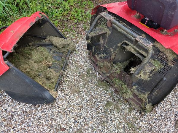
First job is to remove the grass collector, and remove the fixings from the bottom of the grass collector chute.
Now the chute can be withdrawn from the mower:
Now the cutting deck can be removed. Drop the cut height selector to the lowest level - this will take the tension off the hangers that support the back of the deck. Pull on the spring loaded release bolt toward you to allow the hanger to pull free of the deck. Return the cut height leaver to the highest position to lift the carrier drop arms back out of the way.
Now set about freeing the front of the deck. The deck will now slide forward a bit, and the bottom fo the front handing bars will move in the elongated slots, allowing them to be lifted clear of the deck. The deck drive belt can also be removed from round the big "power take of" pulley
Slide the deck out, and set it aside, we don't need this for now:
Access to the rear section of the mower where the rear axel and drive system is located, is rather limited. Some of it can be seen through the rear grass exit port, but for better access can be found under the battery.
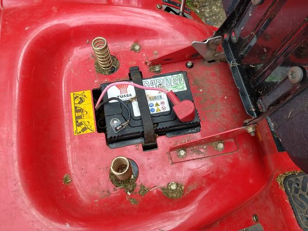
So, disconnect the leads from the battery (-ve first to save any nasty shorts with your spanner, since all the metalwork on the mower is connected to the -ve). Remove the battery and its rubber retaining strap from the battery tray, and lift out the battery. Once the battery is out, the battery tray will also lift out revealing access to the mechanicals below:
Replacing the pulley bearings
The next stage was to fix the bearing. To do this unbolt the three bolts that hold the bearing carrier onto the mower frame. This can be done via the battery access hole. The bearings are a snug but not particularly tight fit and can be pushed out with your thumbs.The hosing then cleaned up, and any dirt, rust, and bits of failed bearing removed!
The new bearings can be pushed back into the housing, and it bolted back in place. The pulley shaft can now be taped back into the bearings, and the retaining bolt and washer re-fitted to hold the pulley in place.
For the next stage, easy access to the underside of the mower is required. Rather than try to work under it, I elected to tip it onto its side (this is not too difficult once the cutting deck removed since this is a heavy part with a low centre of gravity). A strategically placed roll of offcut carpet was placed to give it a soft landing.
When tipping it, tip it onto its right hand side - this keeps the carb uppermost and stops it flooding. Also do it when the petrol tank is close to empty.
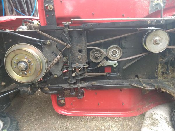
We can now see the layout of the drive system.
The drive system - how it works
These mowers have a belt driven Continuously Variable Transmission (CVT). There is no conventional gearbox and there are no changeable gears. The engine speed is set by the throttle leaver next to the steering wheel, the direction is set by the Forward - Neutral - Reverse selector to the left of the rider (the changes being implemented in the diff), and the movement is all controlled from a single "go" pedal. The further you push the peddle, the faster the mower goes - all without altering the engine speed.
Anyone who has studied the drive system of old "Variomatic" DAF cars (later acquired by Volvo) might have an idea how this is accomplished.
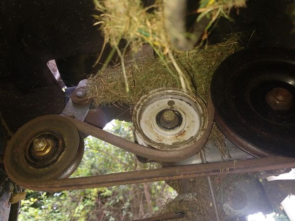
The first (longer) drive belt it looped round a small pulley on the output shaft of the motor. It then passed to an intermediate dual vee pulley toward the back of the mower. The belt in its rest state is fairly slack, but it also passes through a pair of idler wheels in the middle. One of these is fixed in position, but the second can be rotated through a 45 degree arc by pushing the go pedal. This has the effect of lengthening the path of the drive belt, pulling it more tightly onto the pulleys.
This achieves two things: it provides a clutch action for the drive - with the belt slack, the motor power is not delivered to the drive and the engine can "idle" without the mower moving even if left in forward or reverse. The second is to control the effective gearing.
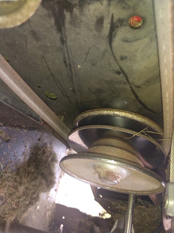
The gearing is controlled by the "magic" double vee pulley. This has a pair of deep vee pulley slots in in. The top and bottom vee profiles are fixed, however the centre section with two vee sides is free to slide up and down on a short shaft between the top and bottom pulley faces.
The power input belt is looped round the top pulley, and output belt that goes to the rear differential, loops round the bottom section. The output belt has a spring loaded tensioner on it. So in the "rest" state the lower belt pulls more tightly into its pulley. This forces the free centre pulley section to slide up. That means that the top input belt is forced into a large circumference route round the pulley, and output shaft gets a much smaller circumference path.
As the rider pushes the go pedal, it tightens the input belt. First this engages drive - with a low effective gearing - the large input pulley circumference and small output pulley circumstance giving a higher mechanical advantage. However as the pedal is depressed further, the force exerted on the pulley by the input belt starts to exceed that of the spring tensioner on the output belt. This forces the floating pulley section downwards. Reducing the input belt circumference, and increasing the output belt circumference - giving the effect of a "higher" gearing. With the go pedal fully depressed, the input belt will be pulled deep into the top grove and the output belt forced right out to its maximum circumference - giving the highest gearing possible and the most travel speed.
If the load on the mower increases (say from towing a heavy trailer), this will increase the drag on the output belt, increasing the effective tension on it, and it will "push back" against the floating pulley, causing the gearing to lower slightly - reducing speed, but increasing torque - automatically compensating for the load.
Changing the front drive belt
The first belt to tackle is the longer "input" belt. This passes round the smaller pulley on the motor output shaft. It has a number of metal fingers that are placed close to it which prevent it from falling out of position on the shaft when the belt is slack. However this also means that it is not possible to remove of fit a belt with the pulley in this position.
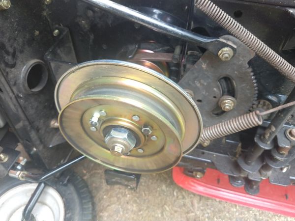
To free the belt it is necessary to move the pulley away from the motor a bit so that it can clear the metal retaining fingers. To do this you will first need to remove the smaller of the two bolts on the bottom of the big PTO pulley (place a large spanner on the big nut and hold it steady, and undo the smaller bolt head).
You can remove the bolt completely, and the whole pulley and PTO clutch and pulley will slide down the motor output shaft. However there is a metal L bracket that will prevent the pulley coming right off the shaft. This will allow space for the old belt to be removed and the new one placed onto the motor pulley.
However there is one more obstacle - the spring loaded linkage that connects to the PTO control leaver from the blade engage leaver to the left of the steering wheel. With the blade control in the "off" position there is not much tension on the springs. The bolt that holds the ends of the springs can then be removed.
You can now place the new belt over the pulley, and one side of it can be pushed through the channel above the steering sector toward the back of the mower. When most of the belt has been pushed through, the remaining loop of belt can be snugged round the motor output pulley, and held in place while the pulley assembly is pushed back onto the motor shaft. Take care that the belt remains inside all of the metal fingers that surround the pulley, and that it passes through the guide bars that are bolted to the underside of the motor platform.
Replace and tighten the main bolt on the PTO/Clutch assembly.
The last bit is easy, loop the other end of the belt round the top CVT pulley, and then pass it between the speed control idler pulleys.
Changing the rear drive belt
The rear drive belt is not too difficult to change, however there is again an obstruction, since the F-N-R direction control level bar passes through the belt, this means you can't actually get a belt into place with it in the way. There is also a small section of flexible conduit with a single wire contained in it.This fixes to an electrical terminal on the rear differential / direction control. This wire is used to implement the interlock that cuts the motor ignition if the mower is put into reverse with the blades running. Without this connection that interlock will not work.
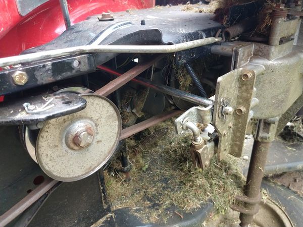
So you will need to withdraw the "R style" cotter pin from the bottom of the direction control lever shaft, as well as the smaller cotter pin on the top of the linkage to the direction control lever on the diff. With both removed you can now slide the shaft out of the retaining bracket, and also free it from the linkage to the diff allowing the belt to be fitted in place
The belt fist passes a larger black pulley on the top of the diff. The section toward the centre line of the mower passes straight through - just touching one side of the diff pulley. The other side is wrapped around the diff pulley by a fixed idler wheel.
The end of the belt does a final lap around a spring loaded tensioning wheel. When the old belt is removed, this will spring back toward the rear of the mover, you will need to pull this into the position shown below to get the belt in place. Note that the spring on this is fairly strong, but you can help lever it into place by placing a long screw driver or small pry bar through the back grass port of the mower, and using the edge of the port as a fulcrum.
Reassembly
That is the belts changed.
Now reinstate the direction leaver linkage by replacing the cotter pins. (I also greased all the moving bits that looked like they might benefit after doing this)
Tip the mower back onto its wheels. Re-attach the cutting deck. Note that the lift hangers have two possible holes that can be used to engage the spring bolts on the deck. Unless you have a bowling green to mow, you probably want the upper set of holes and this allows slightly longer / rougher grass cuts).
Refit the grass output chute - take care that the nose of it sits under the metal guide on the top of the deck, and does not ride above it where it could contact the moving deck belt.
Refit the battery tray, the battery, the retaining strap, and finally refit the battery terminals (+ve first).
Refit the grass collector.
You should now have a fully working mower, with smooth and quiet forward and reverse drive.
