Built in media centre
Introduction
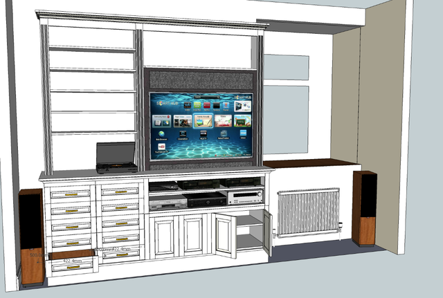
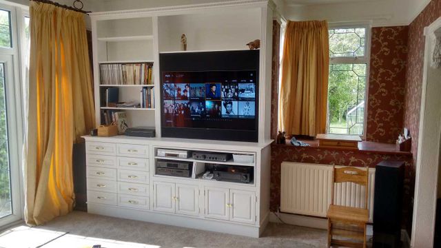
Ever since doing the Classic large bookcase and cupboard I had harboured a desire to create something in the same style to be used as an integrated AV storage unit. The design goal was to provide storage for lots of CDs, a place to install various bits of AV gear and make them easy to access and use, plus space to mount a TV, while hiding speakers etc. If it could have some more shelves for books and even LPs even better.
The stumbling block was coming up with an aesthetically pleasing design that also met the requirements. After a few iterations of sketchup models, the above design was selected.
Design
The construction was designed to look like a fairly classic bit of "built in" Victorian carpentry (if one glosses over the whole anachronism of a Victorian era AV centre!) The construction technique was to be more "smoke and mirrors" however - lots of sheet goods assembled into boxes and then decorated with some slightly fancy face frames to make it look pretty.
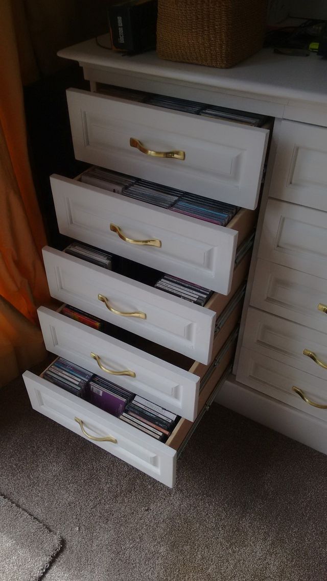
It needed large drawers to hold CDs since the last seven drawer unit I built 20 odd years ago (the first bit of proper furniture I made) was long since full. Decent drawer runners to make them easy to use would also be good. Books shelf space also soon seems to get consumed quickly, so some more of that. Getting the AV gear out of the HiFi rack and from low down under the old TV would also be nice along with a space to hide some wiring, and bits of sound system like the 5.1 centre speakers was also on the list.
Construction
Working from the sketchup model I created a cut list in a spreadsheet. Then I used the free version of MaxCut 2 to allocate those pieces to sheet goods and work out the total requirement for sheets. The cabinets were to be made from a mixture of 2/4" ply and MDF. Drawers from 1/2" ply, and backs etc from 3/8" MDF. Normal PAR softwood for all the face frames and detailing.
Most of the main units were in one way or another a simple box. To make assembly easier and the result a little stronger, the edges of these were usually rebated on a table saw with a dado stack fitted (this makes registration at the corners far more positive). The boxes glued and either pin nailed or screwed together (with the glue doing the bulk of the work).
Drawers
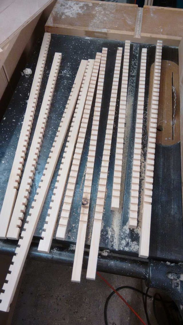
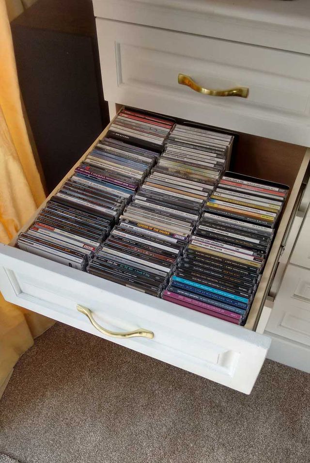
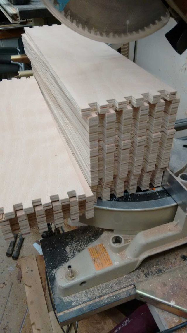
The first bit to tackle was the drawer boxes since these were nearly all the same and could be batched out quickly (two were made a little shorted in drawer length to allow them to close over a socket on the wall behind them). Since these would mostly hold CDs (approx 120 per drawer), they needed to be very strong. The sides were cut from 1/2" ply, and then the corners finger jointed on the table saw with a finger joint sled and a dado blade. This is a very strong and fast construction technique, since multiple sides can be cut at once. The drawers were to have an applied on front that was both wider and taller than the box. This would hide the drawer runner. The base was cut from 5mm ply and a rebate cut on the table saw to create a groove for it to sit in. (all the sides could simply have a through rebate, since the drawer front would hide the notch). The top edge of the ply in each drawer was lipped with soft wood strips to hide the edge.
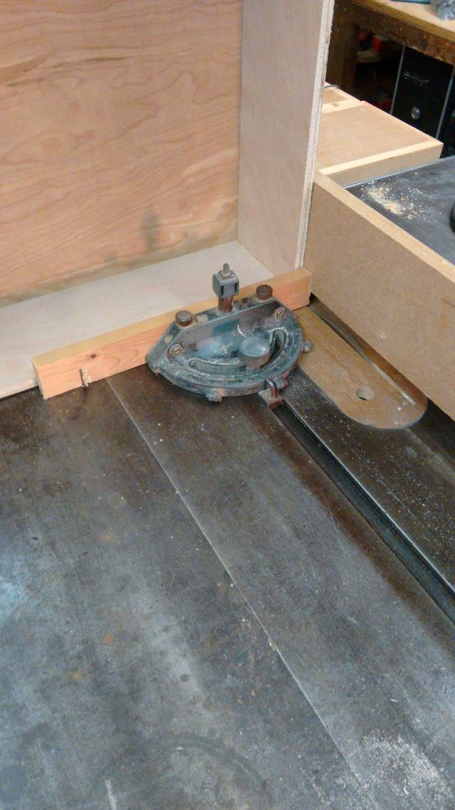
Normally its easier to cut the fingers slighter deeper than they need be be, and they then can be trimmed flush after assembly. Since there would be 80 edges to trim flush here, a simple jig was setup on the table saw with a secondary fence clamped to the side of the main one - but above the blade. With careful adjustment This created a space where the protruding fingers could be run past the blade such that it just glanced the surface, trimming the joint flush.
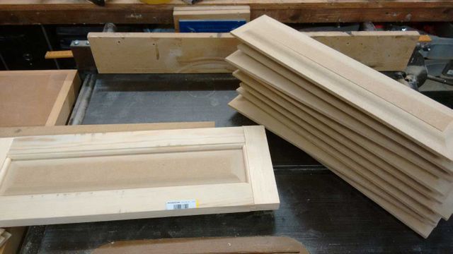
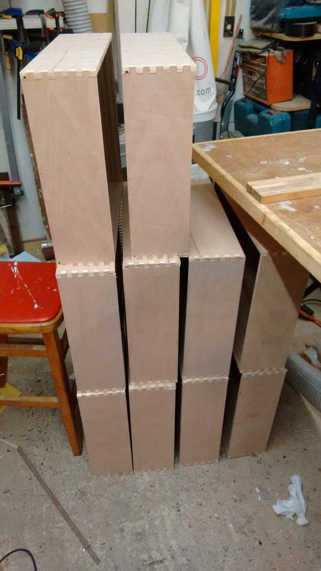
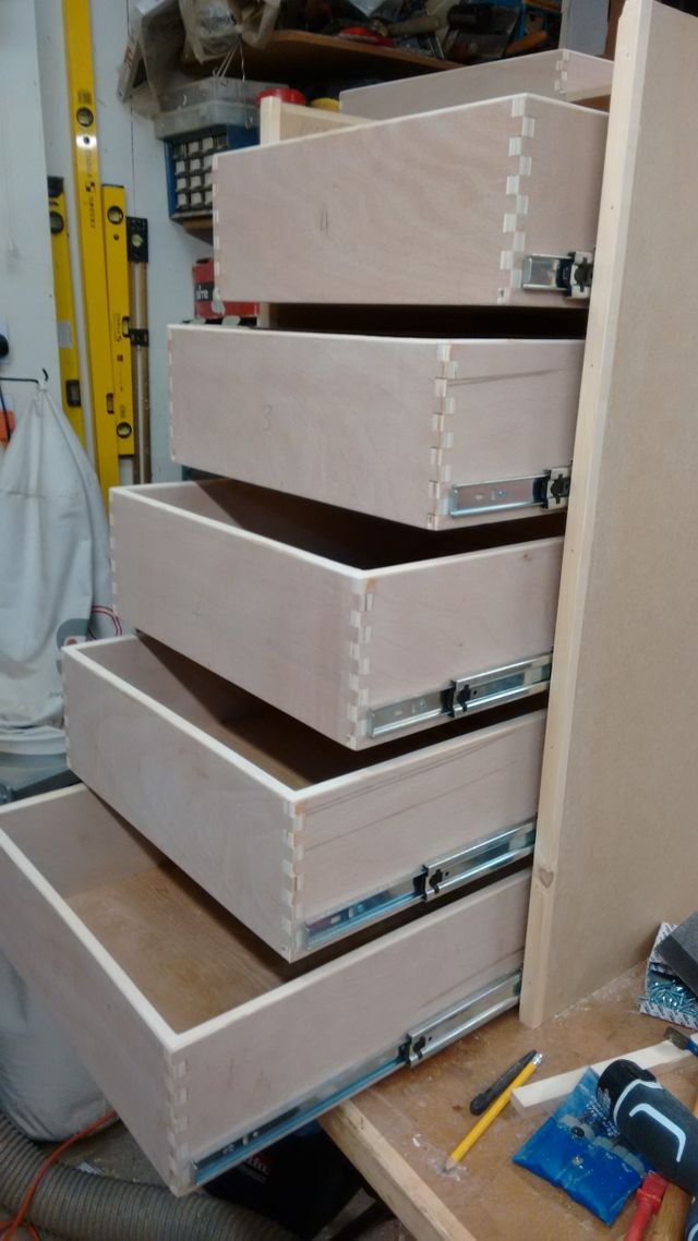
Once all the drawers were complete, these could be stacked out of the way for later:
Drawer Cabinets
The Drawer cabinets were done next. These are nothing more than a couple of sides, a back, and a partial top and bottom just to hold things square. The front edges were lipped with softwood.
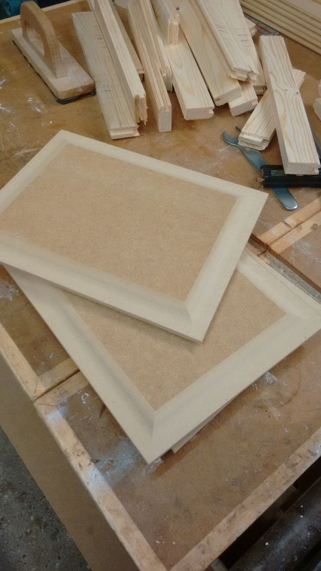
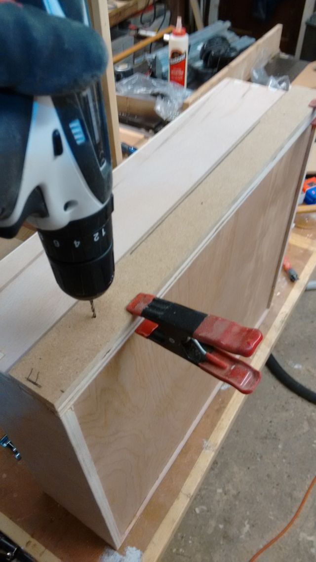
Once they were done the drawers could be fitted. To make the job as simple as possible, some drilling guides were made from 9mm MDF. One for the screw holes that fix the runner to the drawer itself:
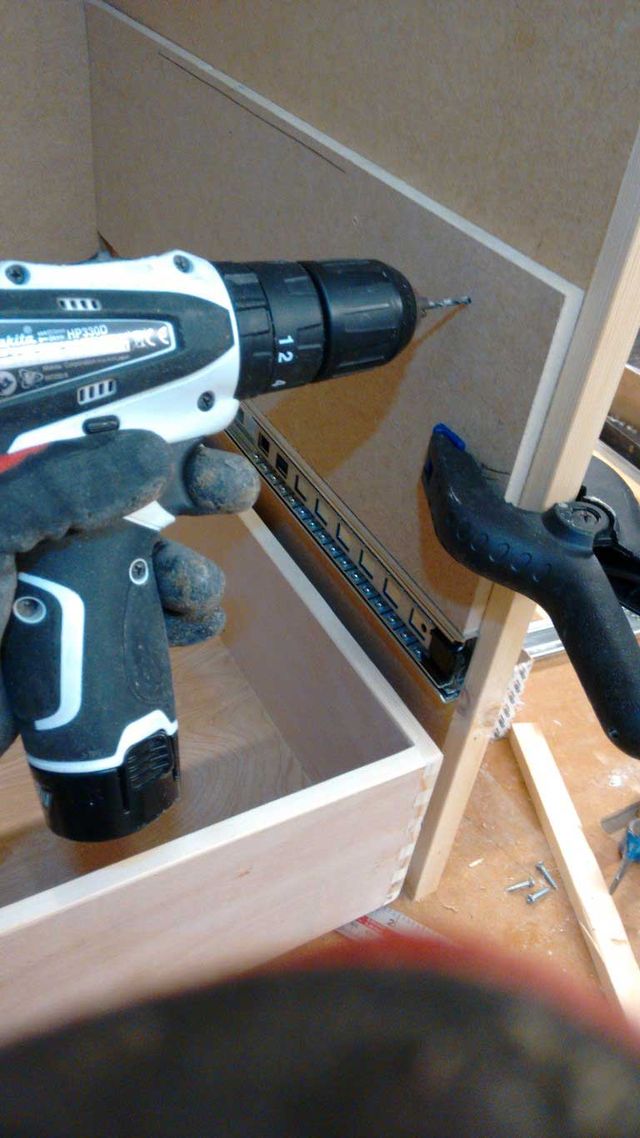
And a second one to set the spacing in the cabinet:
Once all the runners were screwed on:
The drawer units could be stacked out of the way for the next job.
Plinth
Before the base units could start to be setup beside each other, the plinth was needed. It tends to work better when this is made separately from the units, so that it can be installed first and levelled up before anything else goes in. I have also learnt that its worth taking the time to wedge and level it up in the workshop as well for doing the test assemblies, since any errors in level etc will get copied into other parts during assembly if you are not careful.
Construction error number 2
It was about this time, it became obvious something was not working out as it should. Things were not as square as they should be, and some cuts not straight. This was initially hard to explain, since all the sheet goods had been broken down with a sawboard and then often trimmed to size after on the table saw. After some head scratching I realised that my long sawboard had warped, and was cutting long curves! So I used the factory edge of a new sheet of MDF to recut the fence on the sawboard with a router and an edge guide fence.
Some of the errors could be hidden with some offsets in the face frames, other fixed with a re-cut, but some were still lurking to show up later.
AV Base Unit
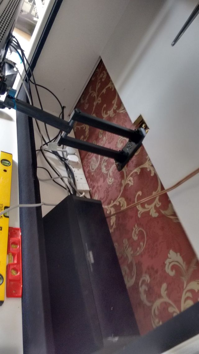
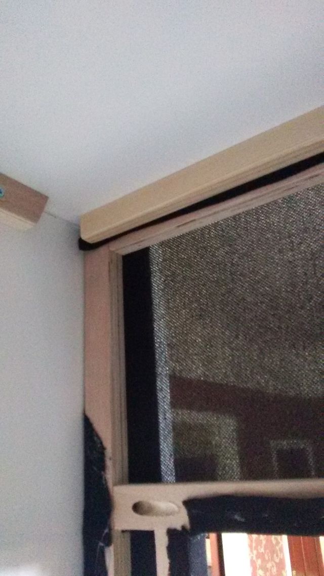
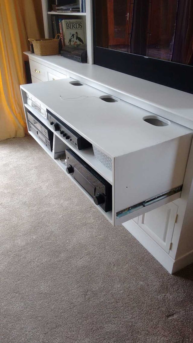
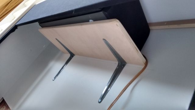
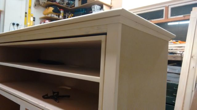
The AV base unit is basically wide box with cupboard doors on the bottom, and huge hidden drawer in the top section. The large drawer is basically a box with a shelf in it, and the drawer runners set into rebates on the side so as to achieve a flush finish round the edge. The purpose of the sliding shelf arrangement was so that the whole unit would slide out, revealing access holes to allow one to reach behind the AV gear for routing cables and making connections. The sliding shelf was also a few inches short of full depth to leave space to allow wires to pass up behind it from the cupboards at the bottom and into the TV Unit at the top. Large oval access holes were cut with a router following a template made from some thin ply.
Plinth Error
Once the base units were placed side by side, it became obvious a fairly fundamental error had been made in the length of the plinth!
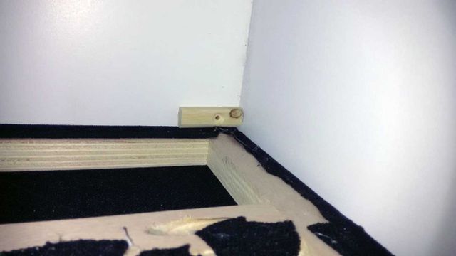
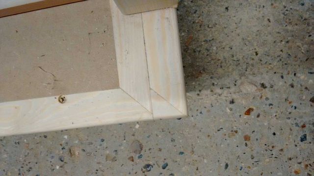
So an extra wide lipping had to be planted on the end to make it long enough.
Base unit worktop
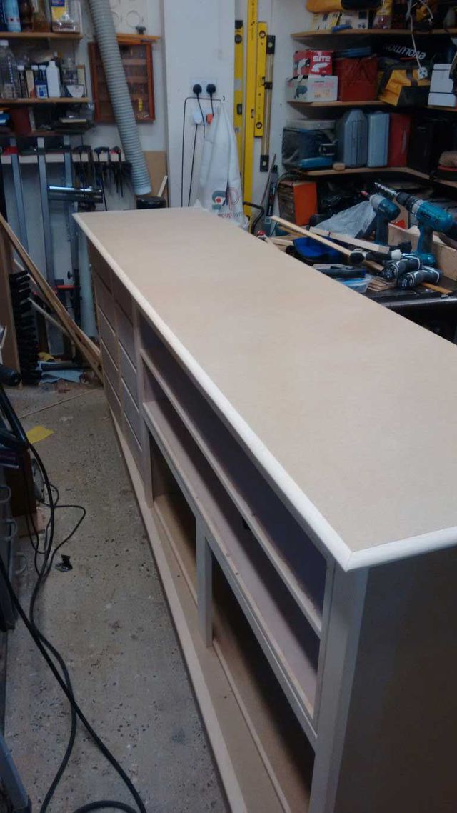
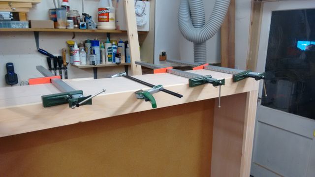
With all the base units on their plinth, the cover moulding and worktop could be installed:
(its about now another wonky board error showed up in the slight change in gap around the AV drawer)
With the whole base unit set assembled there is also very little space left to work in the workshop! I think I have found the size limit of project that can be built in the space!
Bookshelves and TV unit
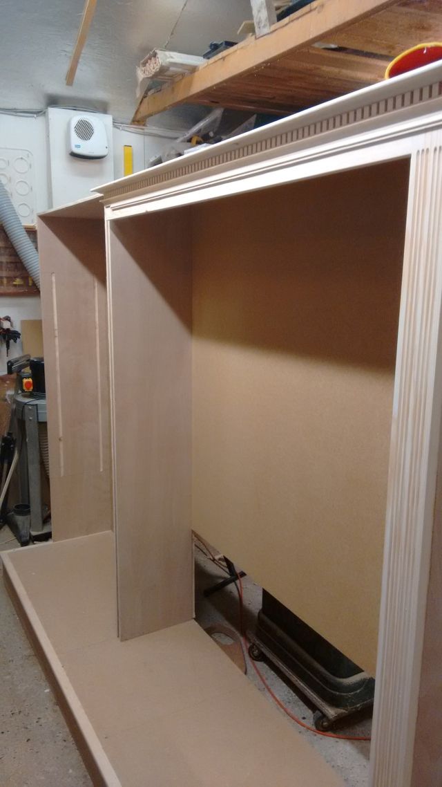
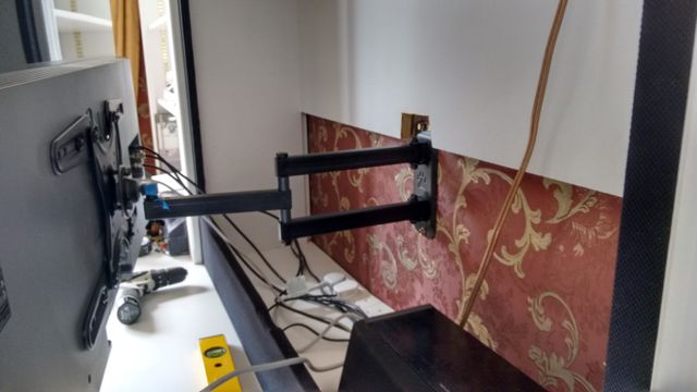
With the base units stacked away, I could start on the top units. These were just ply sided boxes with MDF top and backs. The larger TV unit box had a 3/4" thick back so that things could be fixed directly to it if required.
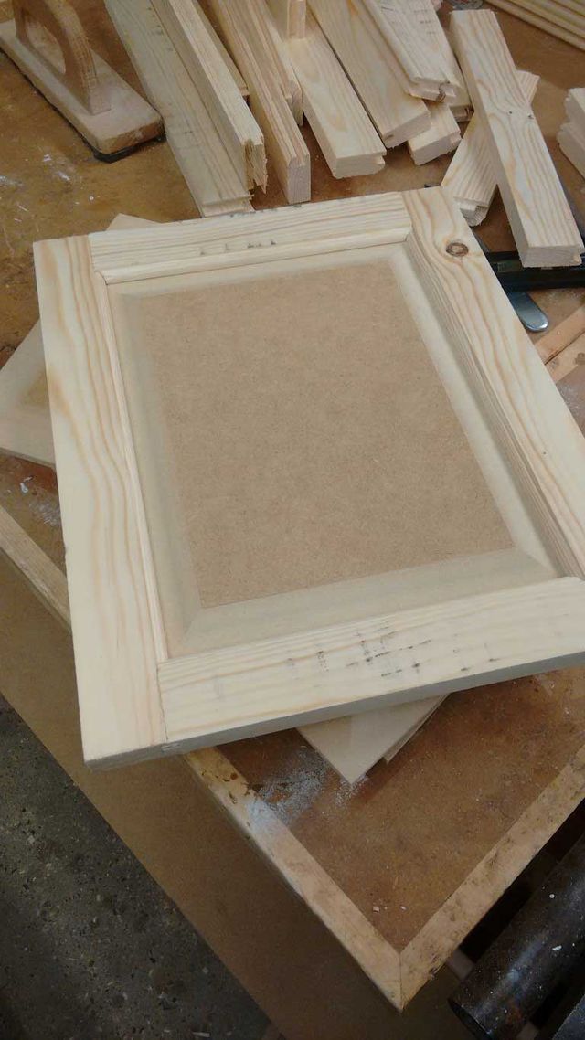
The face frames were glued and biscuit jointed to the boxes (pocket screws could be used only in placed where they would not be visible.
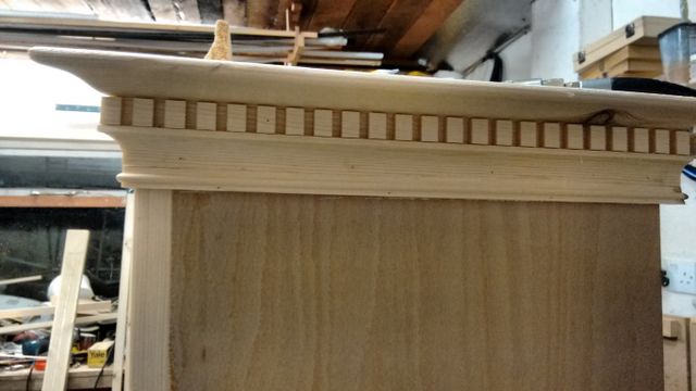
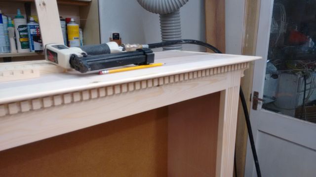
Some of the detail work was done on the router table prior to fixing the face frames such as the flutes in the uprights. The chamfer on the edges was added in place after. The mouldings could also then start to be built up from sections. Starting with the top crown moulding and dentil moulding:
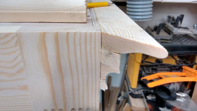
These were fixed with glue and some 23 gauge pin nails. The corner detail shows how the four bits of moulding (crown, dentil, cove, and reed) fit together:
