Difference between revisions of "ELCB"
| Line 90: | Line 90: | ||
==Simplified Test Procedure== | ==Simplified Test Procedure== | ||
| − | The following is easier and can check that an ELCB functions correctly, but is not the procedure required in the 14th edition. Switch off [[fusebox]](es). Disconnect Frame [[wire]] from ELCB. Apply a low power 45v transformer to ELCB's F & E terminals, it should trip. Reconnect Frame wire. It is important for [[safety]] to never permit the fusebox to be powered while Frame is disconnected. | + | The following is easier and can check that an ELCB functions correctly, but is not the procedure required in the 14th edition. Switch off [[fusebox]](es). Disconnect Frame [[Cable|wire]] from ELCB. Apply a low power 45v transformer to ELCB's F & E terminals, it should trip. Reconnect Frame wire. It is important for [[safety]] to never permit the fusebox to be powered while Frame is disconnected. |
==Should I replace it?== | ==Should I replace it?== | ||
Latest revision as of 20:32, 28 September 2017
The term Earth Leakage Circuit Breaker (ELCB) was originally used to describe two classes of device. The Voltage Operated ELCB or "VO ELCB" and the Current Operated ELCB. Current Operated ELCBs are now known as RCDs, and their function is described in the RCD article. This article is specifically about the Voltage Operated version.
The VO ELCB is an obsolete style of circuit breaker designed to limit indirect contact shock severity by detecting a voltage rise on the earthing system of an installation, and automatically disconnecting the supply should the voltage detected exceed a safe limit. When introduced they represented a major improvement in safety of electrical systems - especially those that used TT Earthing.
This article describes their typical use in domestic premises, and how they were tested.
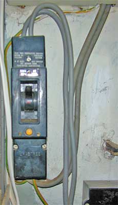
Example VO ELCB
What problem they solve
Before the use of ELCBs on TT earthed installations, the relatively high impedance of the earth rod (or water pipe connection etc) could result in a failure to blow a fuse under earth fault conditions (e.g. shorting live to earth). This could leave all the earthed metalwork in the installation at live potential. This is a major shock risk, and consumes a lot of electricity.
Installations with an ELCB enabled TT earthed installations with high earth impedance to be properly protected in an EEBADS (Earthed Equipotential Bonding and Automatic Disconnection of Supply) system in the same way as was normal for TN systems. Wiring regs required all new installs to have EEBADS from the mid 1950s onward.
Principle of operation
An ELCB detects a rise in voltage of the building's earthing system (called the Frame) (as may result from an earth fault) compared to the voltage on the earth rod (the 2 are only connected through the ELCB). When enough rise in voltage to cause a hazard is detected (50v), the ELCB disconnects both poles of the supply. Effectively the ELCB acts as a bistable relay.
A common misconception is that parallel paths to earth from the 'frame' cause an ELCB to not work. This is not correct, as the job of the ELCB is to disconnect the supply only if the earth reaches an unsafe voltage. Extra parallel earthing paths merely change the level of leakage current at which an unsafe voltage is reached causing the ELCB to trip, and improve safety.
Connection
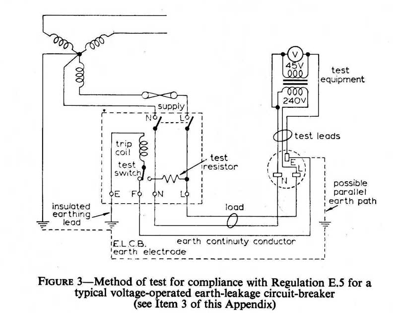
The supply live and neutral are connected via the ELCB. The main earth connection also passes through the device. The earth connections are usually referred to as "Earth" and "Frame" (marked E and F on fig 3 below), with Earth being connected to the earth rod, and the Frame being connected to the house earthing system (typically the earth bus bar in the CU.
Known limitations
There are some known limitations of these devices (hence they have been superseded by RCDs)
- They don't detect leakage to earth unless it passes through the ELCB. Shock/injury from direct contact to a live part, and contact to earth via an independent path aren't detected. (30mA RCDs now used do much the same job, but also protect against shock by touch.)
- They introduce an extra connection into the building's main earth path, increasing risk of disconnection.
- They are not easily integrated into buildings of multiple occupation since it is not always easy to completely separate each individual dwelling's earthing systems from the others. This can cause one dwelling's electrical fault to trip another's ELCB.
Another serious problem is that in practice disconnection of earthing is not uncommon with ELCBs. RCDs don't need an earth connection to work (there are some with added features needing an earth) so this hazard is absent with RCDs.
ELCBs were criticised for their false positive trips, but for the most part they behaved much better in this respect than RCDs used now.
Test Procedure
Testing these is actually quite difficult now since none of the modern off the shelf test gear is setup for their testing these days. Hence if you need to do this, you will need to "roll your own".
From the now superseded 14th edition of the wiring regs: (commentary included in boxed sections)
(2) EARTH-LOOP IMPEDANCE TESTS (REGULATION E.4)
These tests should be made with the cross-bonds required by Regulations D.10-13 in place.
Note that this is contrary to current testing practice of earthing systems where the
bonding conductors are disconnected first to remove any fortuitous effects they
may have on lowering loop impedance
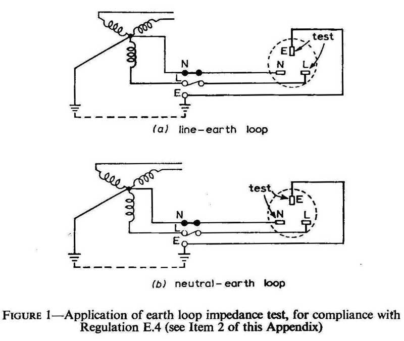
- The earth-fault-loop path (line-earth loop) comprises the following parts, starting and ending at the point of fault (see also Figure 1)—
- the earth-continuity conductor,
- the consumer's earthing terminal and the earthing lead,
- the metallic return path where available, which may consist of the metallic cable sheath or the continuous earth wire of an overhead line or, in :*the case of Protective Multiple Earthing (P.M.E.), the neutral conductor, or where no metallic return path is available, the earth return path, and
- the path through the earthed neutral point of the transformer and the transformer winding, and
- the live conductor.
The method used may show the loop impedance in ohms; alternatively it may give a direct indication of the maximum permissible fuse rating or setting of a circuit-breaker, or an indication whether a fuse or circuit-breaker of a given rating will operate satisfactorily under fault conditions.
(a) Tests in Line-earth loop
- These tests may be achieved by an instrument which determines the current flowing when a known resistance is connected between the live conductor and consumer's earthing terminal. In using such an instrument, care should be taken that no ill effects can arise if the earthing circuit is defective.
(b) Tests in Neutral-earth loop
- Except when the system is earthed by Protective Multiple Earthing (P.M.E.), it is permissible to test the neutral-earth loop instead of the line-earth loop. This may be achieved by a method which injects current into the neutral-earth loop, preferably by means of a transformer fed from the mains, or alternatively from a d.c. source the polarity of which is rapidly and continually reversed. The instrument employed fhust be so designed, or used, that its indications are not affected by neutral currents flowing in the system. In using such an instrument, care should be taken to ensure that no ill effect can arise if the circuit tested is defective. Measurements on systems fed from small transformers may require compensation, to include an allowance for the impedance of the windings of transformers, balancers, etc. If a test with rapidly-reversed d.c. is made on an a.c. installation, it should be ensured, by inspection, that no inductor is incorporated in the earth-continuity conductor.
When a measurement on an a.c. system is made with less than 10 amperes a.c., or with rapidly-reversed d.c., and the earth-continuity conductor is wholly or mainly of steel conduit or pipe, the effective value shall be taken as twice the measured value less the value measured at the consumer's earthing terminal. In all other cases the effective value shall be the measured value, subject to any necessary adjustment for impedance of supply transformers, balancers, etc., as mentioned above.
(3) TEST OF EARTH-LEAKAGE CIRCUIT-BREAKERS (REGULATION E.5)
For the purpose of this test a voltage not exceeding 45 volts, obtained from a double-wound transformer connected to the mains supply, shall be applied across the neutral and earth terminals (or neutral and frame terminals of a voltage-operated earth-leakage circuit-breaker) and the circuit-breaker shall trip instantaneously. The transformer shall preferably have a short-time rating of not less than 750 VA. (See Figures 2 and 3).
Note fig 2 shows a test setup for what in effect are modern RCDa and hence is not included here.
When, in accordance with the requirements of Regulations D.10-13, cross-bonding 10 other services is carried out in an installation where a voltage-operated earth-leakage circuit-breaker is provided, this may result in a direct earth connection of low impedance being introduced in parallel with the path through the earth-leakage circuit-breaker. Thus an increased value of earth-leakage current would need to flow before the circuit-breaker came into operation, and in some instances the cross-bonding may well remedy the deficiency which originally gave rise to the need for the earth-leakage circuit-breaker. These effects are not harmful; it is common practice to use the best solid earth available (e.g., suitably spaced earth electrodes) in parallel with an earth-leakage circuit-breaker. The circuit-breaker would still be effective in preventing the exposed metalwork of the installation from rising to a dangerous voltage.
(4) MEASUREMENT OF CONSUMER'S EARTH-ELECTRODE RESISTANCE
The following procedure shall be adopted where it is desired to measure the resistance of the earth electrode, e.g. where the installation fails to satisfy the earth-loop impedance test or where it is desired to check the continuity effected through an earth electrode. (See also Figure 4).
Figure 4 is not reproduced here, however its equivalent is shown in the TT Earthing article.
An alternating current of a steady value shall be passed between the earth electrode X and an auxiliary earth electrode Y placed at such a distance from X that the resistance areas of the two electrodes do not overlap. A second auxiliary earth electrode Z, which may be a metal spike driven into the ground, shall then be inserted half-way between X and Y and the voltage drop between X and Z shall be measured. The resistance of the earth electrodes is then the voltage between X and Z divided by the current flowing between X and Y, provided that there is no overlap of the resistance areas. To check that the resistance of the earth electrodes is a true value, two further readings shall be taken with the second auxiliary electrode Z moved 6m further from and 6m nearer to X respectively. If the three results are substantially in agreement, the mean of the three readings shall be taken as the resistance of the earth electrode X. If there is no such agreement the tests shall be repeated with the distance between X and Y increased.
The test shall be made either with current at power frequency, in which case the resistance of the voltmeter used must be high (of the order of 200 ohms per volt), or with alternating current from an earth tester comprising a hand-driven generator, a rectifier (where necessary), and a direct-reading ohmmeter.
If the tests are made at power frequency the source of the current used for the test shall be isolated from the power mains (e.g. by a double-wound transformer), and in any event the earth electrode X under test shall be disconnected from all sources of supply other than that used for testing.
Simplified Test Procedure
The following is easier and can check that an ELCB functions correctly, but is not the procedure required in the 14th edition. Switch off fusebox(es). Disconnect Frame wire from ELCB. Apply a low power 45v transformer to ELCB's F & E terminals, it should trip. Reconnect Frame wire. It is important for safety to never permit the fusebox to be powered while Frame is disconnected.
Should I replace it?
ELCBs are obsolescent, with many still in use on 1950s-70s installs. They make the use of a local earth rod safe, as long as they're connected correctly and still work.
- Since so many have been found not connected correctly, its worth checking the 2 earth wires are connected, and the main earth wire is still connected to the earth rod.
- Full testing is non-trivial now. Pressing the test button to ensure they trip is worth doing.
While there is no requirement to replace them if connected and working correctly, replacing with an RCD will reduce the risk of injury should one receive a shock (an ELCB does nothing if you connect yourself to a live wire, whereas a 30mA RCD trips very rapidly). Note also that the difficulty of testing properly usually means that it is usually cheaper to simply replace them.


