Difference between revisions of "Large Octagonal garden table"
(bulk image) |
(Draft WIP) |
||
| Line 1: | Line 1: | ||
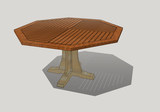
[[image:Octagonal Table Concept.png|640px]] | [[image:Octagonal Table Concept.png|640px]] | ||
| + | |||
| + | ==Introduction== | ||
| + | The green plastic garden table we bought 20 odd years ago was looking a bit shabby (and saggy it has to be said), so a management order was placed for a new garden table. So the question then was, what should it look like? | ||
| + | |||
| + | I have always quite liked the look of the small [[Garden table - slatted top|octagonal table]] that Stan made, however I needed something that could seat up to eight - so it needed to quite a bit larger. There are plenty of small spindly looking octagonal tables one the web, but nothing really floated my boat. So I decided I wanted something a bit closer in scale to a Mouseman dining table (although without the £4k price tag) | ||
| + | |||
| + | So the ubiquitous sketchup model was cobbled together for a table approx 60" wide, and standing around 30" from the floor. | ||
| + | |||
| + | ==Materials== | ||
| + | Since this is an outdoor project, we needed something fairly durable, and for one reason or another I had a number of large oak boards sat in the workshop waiting for a good project. So that decision was easy. | ||
| + | |||
| + | ==Construction== | ||
| + | To avoid oak staining from contact with steel fastenings and moisture, I opted for a traditional style of mortice and tenon joinery. | ||
| + | |||
| + | ===The Base=== | ||
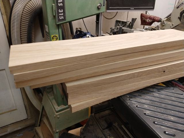
| + | So the first bit to make was the base. This was to consist of a sculpted cruciform set of feet, that would support central column. The column would then be attached to 4 radial "wings" to add some width and heft to the base. (since the design is by nature "top heavy", the base wants to be fairly heavy and the top comparatively light weight). | ||
| + | |||
| + | [[image:Table base stock prepared.jpg|640px|Stock cut to rough size and planed up]] | ||
| + | |||
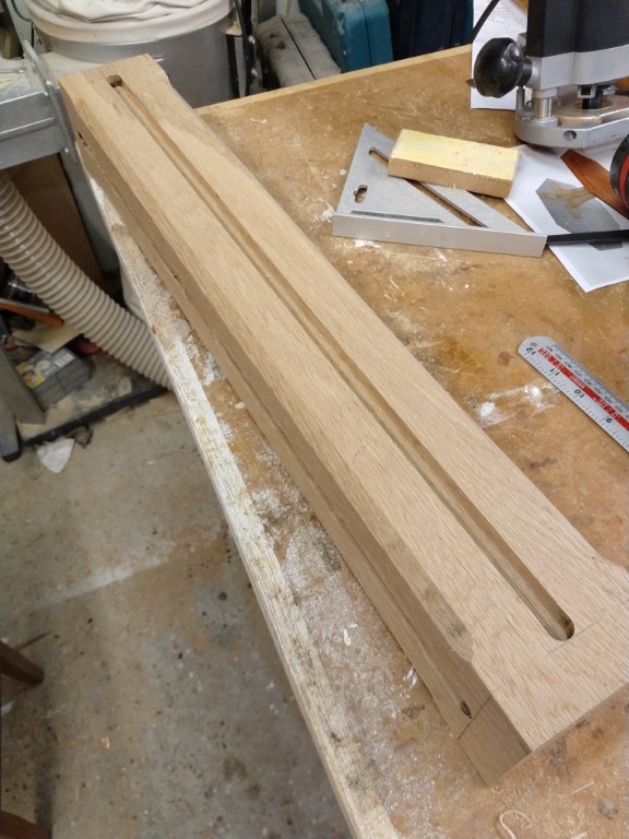
| + | A couple of 2"x2" boards were glued up to make the central column. Some full length mortises were routed into the sides of this, and a decorative "stopped" bevel added to the corners: | ||
| + | |||
| + | [[image:Table base central column routing.jpg|640px]] | ||
| + | |||
| + | Next job was was the "wings" that fit to the sides of the column. | ||
| + | |||
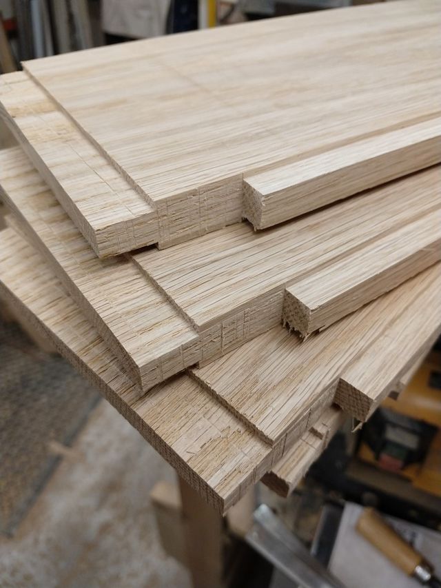
| + | [[image:Table base wing tenons.jpg|640px]] | ||
| + | |||
| + | These needed some tenons cut at both ends and the side, but this was easier to do while they were still rectangular. A quick run past a dado blade on the table saw doing most of the work. | ||
| + | |||
| + | Next we needed the base - this is basically a large cross shape made from two 4"x2" timbers with a half lap saddle joint in the middle. To get the foot profile I started with a sketch of the shape, and transferred this to a bit of spare laminate flooring someone had given me (the thin MDF with a melamine face is quite good for template making, and also nice and easy to work and fineness into smooth curves etc). Then I used the template to trace out the shape onto each leg, before cutting them out on the bandsaw. | ||
| + | |||
| + | The width of the feet meant that I could not use a flush trim bit in a router after, so had to cut carefully, and then do the final shaping using a spindle sander, and finally a random orbit sander with a soft interface pad fitted to get the smooth curves. | ||
| + | |||
| + | [[image:Table base leg routing.jpg|640px|Is there a point in a project you reach "peak router"?]] | ||
| + | |||
| + | The final bit of shaping work for the base was to cut the curve into the wings, and add a small bevel to the edges. So another laminate flooring profile template was made. I used this to draw the curve before cutting close to the line on the bandsaw: | ||
| + | |||
| + | [[image:Table base wing cutting.jpg|640px]] | ||
| + | |||
| + | With this bit it was easy to use the template to make the final finish cuts as well. By Adding a template following bit to the trim router: | ||
| + | |||
| + | [[image:Table base wing trim routing.jpg|640px]] | ||
| + | |||
| + | I could copy the edge of the template to the timber. One thing I had to watch with the curve is that at some point you will find yourself cutting against the grain direction in a way that can make brittle woods like oak chip out. | ||
| + | |||
| + | [[image:Table base wing routing climb cut.jpg|640px| You can see chip out beginning to occur here]] | ||
| + | |||
| + | The solution is to "climb cut" the tricky part of the slope (i.e. cutting in the wrong direction). Climb cuts can be dangerous, but are usualyl ok if you are only removing a small amount of material. The final result is nice smooth shaped profile that exactly matches the template. | ||
| + | |||
| + | [[image:Table base wing finish cut.jpg|640px|]] | ||
| + | |||
| + | ===Base assembly=== | ||
| + | |||
| + | The last bit of work on the base was the assembly. While the side wings can be glued to the central column (Titebond III since its waterproof), because there is a substantial width of cross grain timber in long "with the grain" mortices in the base, I needed a way to fix the wings to the feet in a way that would not cause problems with seasonal movement and humidity changes. So rather than glue these, I decided that allowing for some "slip" in the mortices, and dry fit them using timber pins. The holes in the tenons being suitably widened to allow for movement, and the mortice being cut a bit wider than the tenon. | ||
| + | |||
| + | ====Making walnut dowels==== | ||
| + | This did of course mean I needed some suitable dowels. I decided to opt for walnut since this might make a nice contrast. To make the dowel, I needed a "jig" (calling it a jig is perhaps over egging it a bit), but basically a bit of steel (in this case some fairly heavy gauge angle iron)with holes drilled in it. I could then rip a thin strip of wood off on the table saw, and knock the corners off with a plane. whittle down the ends to leave a small point on one end, and something that will go in a drill chuck on the other. The just using the drill to drive the stick through the hole: | ||
| + | |||
| + | [[image:Dowel making jig 1.jpg|640px]] | ||
| + | |||
| + | Further holes in 0.5mm diameter decreasing steps, allow the dowel to be size as required. | ||
| + | |||
| + | [[image:Dowel jig refining size 2.jpg|640px]] | ||
| + | |||
| + | So it was quite quick to make dowels of any size, and in any timber species: | ||
| + | |||
| + | [[image:Table walnut dowels.jpg|640px]] | ||
| + | |||
| + | |||
| + | ===Base glue up=== | ||
| + | The first bit of base (centre column, and two wings) was a nice easy glue up. However to do the final cruciform shaped arrangement with all four wings required a slightly more complicated setup to get the clamping force in the right place: | ||
| + | |||
| + | [[image:Table Base tricky glue up.jpg|640px|A couple of clamping calws allowing a pair of clamps to pull in the middle bit]] | ||
| + | |||
| + | The small clamps and the splint of wood at the end ensure everything sets up in line. | ||
| + | |||
| + | [[image:Table base assembly.jpg|640px|The completed base assembly]] | ||
| + | |||
| + | Once the central column was complete, it could be set into the feet, and the dowels driven through. | ||
| + | |||
| + | ==The Top== | ||
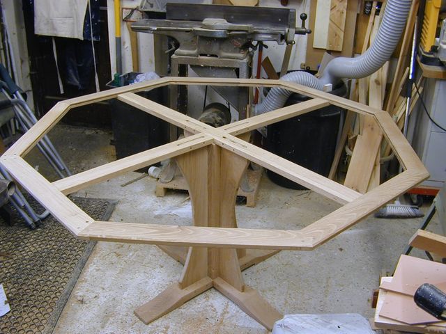
| + | I had designed the octagonal table top as a frame, with slats that would "fill in" the middle bit. The frame would be supported by a pair of crossed "arms" that would sit on top of the base. | ||
| + | |||
| + | For this to work and look good, we needed a very well fitting ring of wood to go round the perimeter of the table. So the first trick was to make sure I could cut the angles accurately on the ring. To test this I made some test pieces out of some very thin sections of scrap pine. | ||
| + | |||
| + | [[image:Table Octagon Angle Test.jpg|640px]] | ||
| + | |||
| + | The joints all looked tight enough, so time to cut the real timbers. The perimeter is made from 2.5" wide stock about 1" thick. | ||
| + | |||
| + | The next decision was to how these sections would join. To get a really strong joint I decided that cutting saddle joints into the ends of each section, would then let me use a substantial slip tenon to join them. | ||
| + | |||
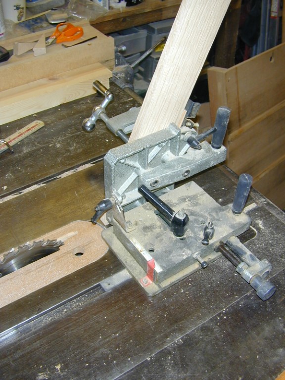
| + | So next I cut the mortice for the tenon using a tenon jig on the table saw fitted with a dado blade: | ||
| + | |||
| + | [[image:Table Tenon Jig Slot Mortise 1.jpg|640px]] | ||
| + | |||
| + | Having done this, the tenons could be glued into place on one end of each segment: | ||
| + | |||
| + | [[image:Table Slip Tenons in place.jpg|640px]] | ||
| + | |||
| + | I then made a drilling jig: | ||
| + | |||
| + | [[image:Table drill guide 1.jpg|640px]] | ||
| + | |||
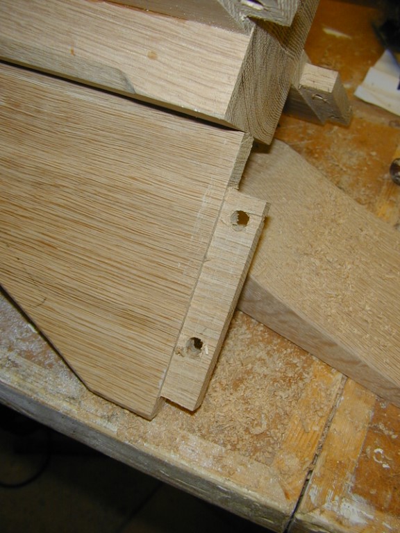
| + | That could be used to consistently place holes through the ends of each segment and the slip tenons. More walnut dowels could be driven though the holes and planed flush to add strength to the joint and some visual appeal | ||
| + | |||
| + | [[image:Table drill guide use.jpg|640px]] | ||
| + | |||
| + | I decided that gluing and clamping up a large octagon would probably be quite tricky. So I figured I could make life much easier if I used the draw bore technique the not only pin the joints, but also pull them firmly together. | ||
| + | |||
| + | So I started by drilling more holes with the guide in the "open" ends of the segments. To prevent the wood chipping out inside the mortice, a small sacrificial "spelch" block could be inserted for support before each drilling. | ||
| + | |||
| + | [[image:Table drill guide spelch block.jpg|640px]] | ||
| + | |||
| + | Each segment could then be dry fitted, and the brad point frill bit used to make the holes, used as a punch to mark the position where the holes intersect the tenons. Next drill the tenons, but moving the hole position about 1/32" closer to the shoulder of the --- TBC | ||
| + | |||
| + | |||
[[image:Table slat fitting 1.jpg|640px]] | [[image:Table slat fitting 1.jpg|640px]] | ||
[[image:Table slat fitting 2.jpg|640px]] | [[image:Table slat fitting 2.jpg|640px]] | ||
| Line 8: | Line 124: | ||
[[image:Table Slat tenon 1.jpg|640px]] | [[image:Table Slat tenon 1.jpg|640px]] | ||
[[image:Table Slats taped in place.jpg|640px]] | [[image:Table Slats taped in place.jpg|640px]] | ||
| − | |||
| − | |||
[[image:Table Tenon Jig Slot Mortise 2.jpg|640px]] | [[image:Table Tenon Jig Slot Mortise 2.jpg|640px]] | ||
[[image:Table tenon seasonal change allowance 2.jpg|640px]] | [[image:Table tenon seasonal change allowance 2.jpg|640px]] | ||
| − | |||
[[image:Table top dry fit.jpg|640px]] | [[image:Table top dry fit.jpg|640px]] | ||
[[image:Table top oiling.jpg|640px]] | [[image:Table top oiling.jpg|640px]] | ||
| − | |||
| − | |||
| − | |||
| − | |||
| − | |||
| − | |||
| − | |||
| − | |||
| − | |||
| − | |||
| − | |||
[[image:Table base oiling.jpg|640px]] | [[image:Table base oiling.jpg|640px]] | ||
[[image:Table Base Stained.jpg|640px]] | [[image:Table Base Stained.jpg|640px]] | ||
| − | |||
[[image:Table draw bored joints close up.jpg|640px]] | [[image:Table draw bored joints close up.jpg|640px]] | ||
| − | |||
| − | |||
| − | |||
[[image:Table fist stain application.jpg|640px]] | [[image:Table fist stain application.jpg|640px]] | ||
[[image:Table Frame assembly and glue up.jpg|640px]] | [[image:Table Frame assembly and glue up.jpg|640px]] | ||
| − | |||
[[image:Table plinth closeup.jpg|640px]] | [[image:Table plinth closeup.jpg|640px]] | ||
| − | + | ||
| − | + | [[image:Table Complete on Patio.jpg|640px]] | |
| − | [[image: | ||
Revision as of 21:53, 15 July 2019
Introduction
The green plastic garden table we bought 20 odd years ago was looking a bit shabby (and saggy it has to be said), so a management order was placed for a new garden table. So the question then was, what should it look like?
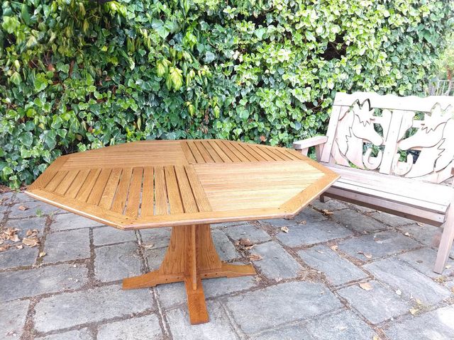
I have always quite liked the look of the small octagonal table that Stan made, however I needed something that could seat up to eight - so it needed to quite a bit larger. There are plenty of small spindly looking octagonal tables one the web, but nothing really floated my boat. So I decided I wanted something a bit closer in scale to a Mouseman dining table (although without the £4k price tag)
So the ubiquitous sketchup model was cobbled together for a table approx 60" wide, and standing around 30" from the floor.
Materials
Since this is an outdoor project, we needed something fairly durable, and for one reason or another I had a number of large oak boards sat in the workshop waiting for a good project. So that decision was easy.
Construction
To avoid oak staining from contact with steel fastenings and moisture, I opted for a traditional style of mortice and tenon joinery.
The Base
So the first bit to make was the base. This was to consist of a sculpted cruciform set of feet, that would support central column. The column would then be attached to 4 radial "wings" to add some width and heft to the base. (since the design is by nature "top heavy", the base wants to be fairly heavy and the top comparatively light weight).
A couple of 2"x2" boards were glued up to make the central column. Some full length mortises were routed into the sides of this, and a decorative "stopped" bevel added to the corners:
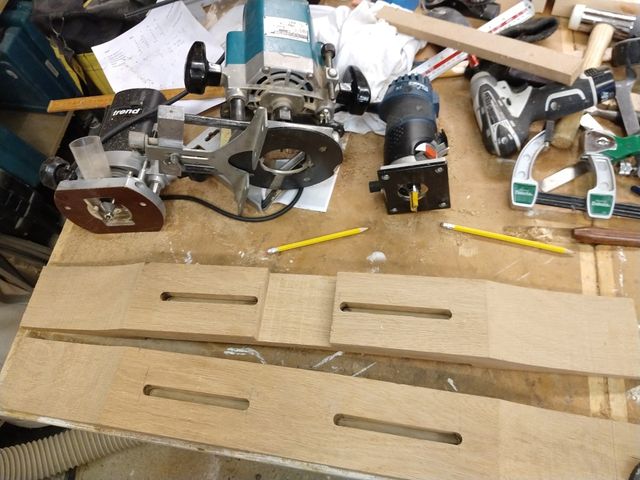
Next job was was the "wings" that fit to the sides of the column.
These needed some tenons cut at both ends and the side, but this was easier to do while they were still rectangular. A quick run past a dado blade on the table saw doing most of the work.
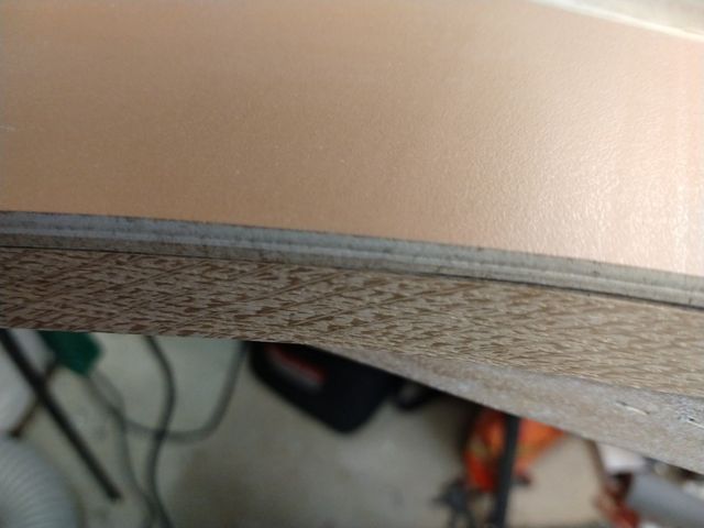
Next we needed the base - this is basically a large cross shape made from two 4"x2" timbers with a half lap saddle joint in the middle. To get the foot profile I started with a sketch of the shape, and transferred this to a bit of spare laminate flooring someone had given me (the thin MDF with a melamine face is quite good for template making, and also nice and easy to work and fineness into smooth curves etc). Then I used the template to trace out the shape onto each leg, before cutting them out on the bandsaw.
The width of the feet meant that I could not use a flush trim bit in a router after, so had to cut carefully, and then do the final shaping using a spindle sander, and finally a random orbit sander with a soft interface pad fitted to get the smooth curves.
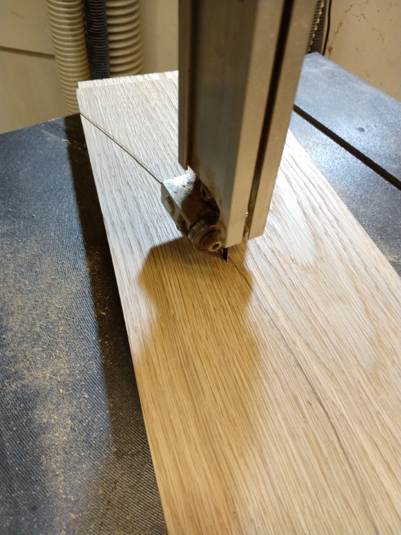
The final bit of shaping work for the base was to cut the curve into the wings, and add a small bevel to the edges. So another laminate flooring profile template was made. I used this to draw the curve before cutting close to the line on the bandsaw:
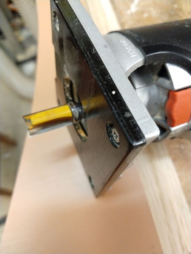
With this bit it was easy to use the template to make the final finish cuts as well. By Adding a template following bit to the trim router:
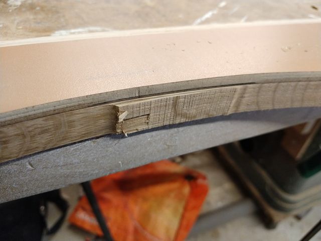
I could copy the edge of the template to the timber. One thing I had to watch with the curve is that at some point you will find yourself cutting against the grain direction in a way that can make brittle woods like oak chip out.
The solution is to "climb cut" the tricky part of the slope (i.e. cutting in the wrong direction). Climb cuts can be dangerous, but are usualyl ok if you are only removing a small amount of material. The final result is nice smooth shaped profile that exactly matches the template.
Base assembly
The last bit of work on the base was the assembly. While the side wings can be glued to the central column (Titebond III since its waterproof), because there is a substantial width of cross grain timber in long "with the grain" mortices in the base, I needed a way to fix the wings to the feet in a way that would not cause problems with seasonal movement and humidity changes. So rather than glue these, I decided that allowing for some "slip" in the mortices, and dry fit them using timber pins. The holes in the tenons being suitably widened to allow for movement, and the mortice being cut a bit wider than the tenon.
Making walnut dowels
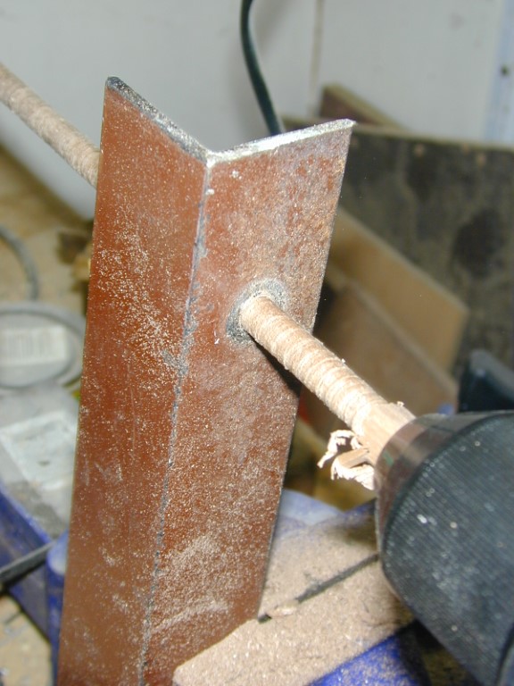
This did of course mean I needed some suitable dowels. I decided to opt for walnut since this might make a nice contrast. To make the dowel, I needed a "jig" (calling it a jig is perhaps over egging it a bit), but basically a bit of steel (in this case some fairly heavy gauge angle iron)with holes drilled in it. I could then rip a thin strip of wood off on the table saw, and knock the corners off with a plane. whittle down the ends to leave a small point on one end, and something that will go in a drill chuck on the other. The just using the drill to drive the stick through the hole:
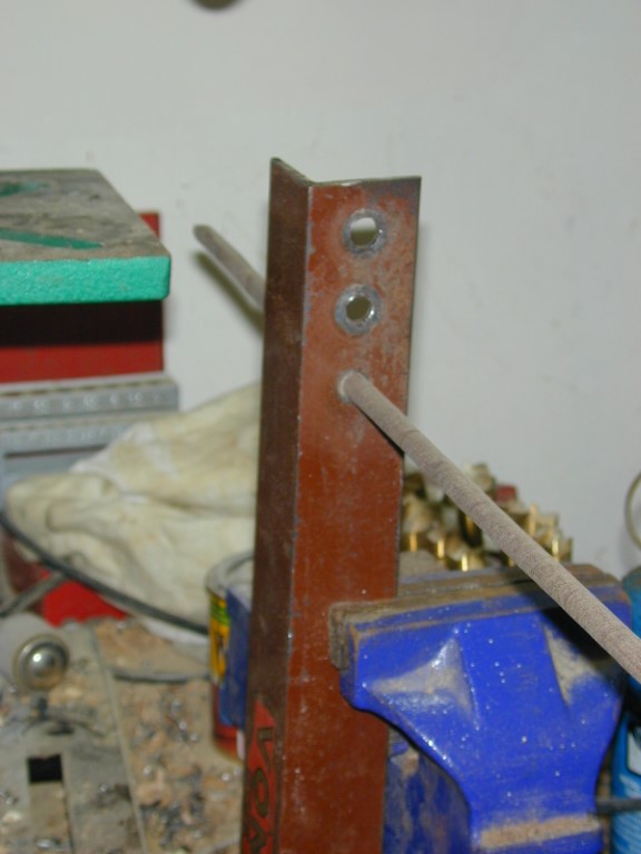
Further holes in 0.5mm diameter decreasing steps, allow the dowel to be size as required.
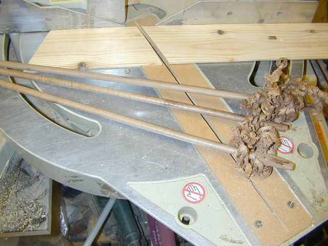
So it was quite quick to make dowels of any size, and in any timber species:
Base glue up
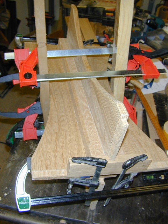
The first bit of base (centre column, and two wings) was a nice easy glue up. However to do the final cruciform shaped arrangement with all four wings required a slightly more complicated setup to get the clamping force in the right place:
The small clamps and the splint of wood at the end ensure everything sets up in line.
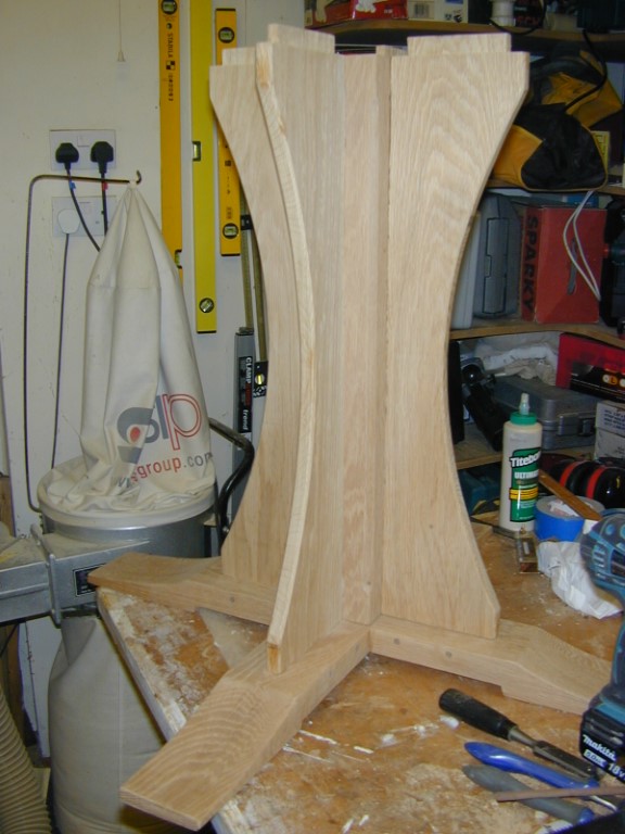
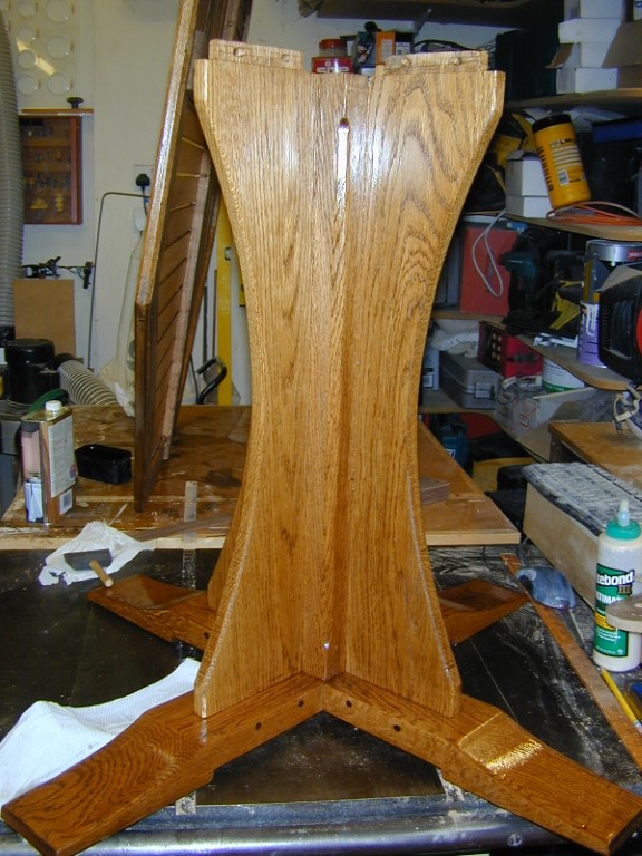
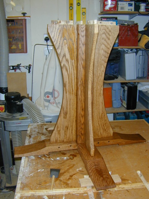
Once the central column was complete, it could be set into the feet, and the dowels driven through.
The Top
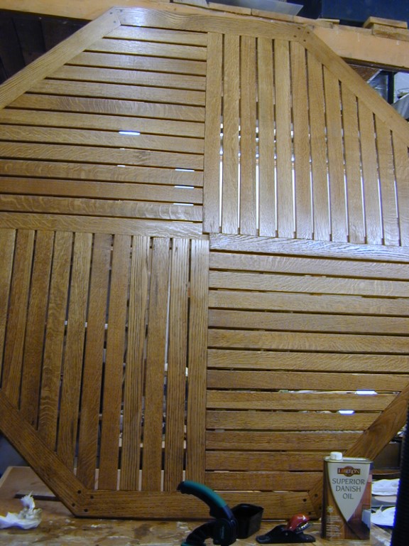
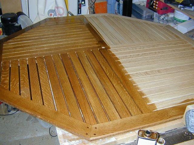
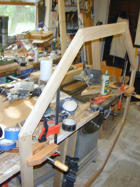
I had designed the octagonal table top as a frame, with slats that would "fill in" the middle bit. The frame would be supported by a pair of crossed "arms" that would sit on top of the base.
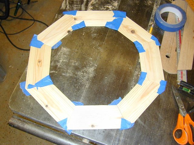
For this to work and look good, we needed a very well fitting ring of wood to go round the perimeter of the table. So the first trick was to make sure I could cut the angles accurately on the ring. To test this I made some test pieces out of some very thin sections of scrap pine.
The joints all looked tight enough, so time to cut the real timbers. The perimeter is made from 2.5" wide stock about 1" thick.
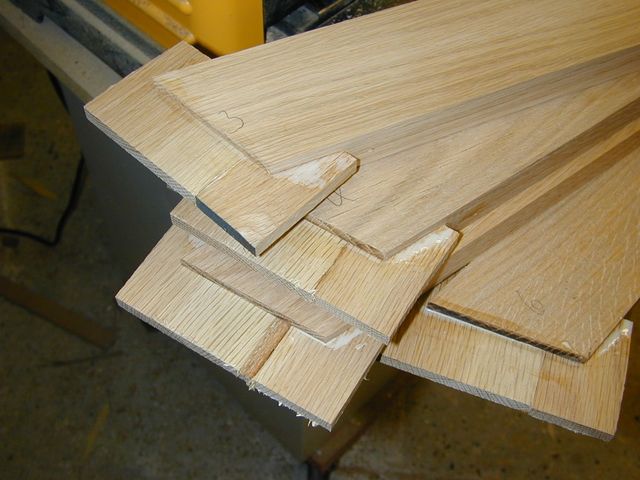
The next decision was to how these sections would join. To get a really strong joint I decided that cutting saddle joints into the ends of each section, would then let me use a substantial slip tenon to join them.
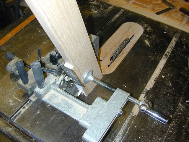
So next I cut the mortice for the tenon using a tenon jig on the table saw fitted with a dado blade:
Having done this, the tenons could be glued into place on one end of each segment:
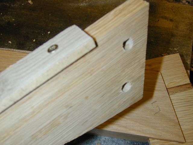
I then made a drilling jig:
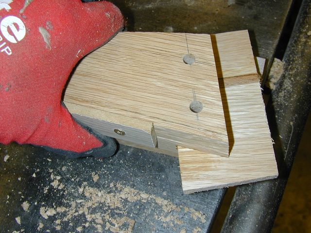
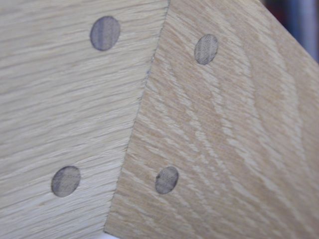
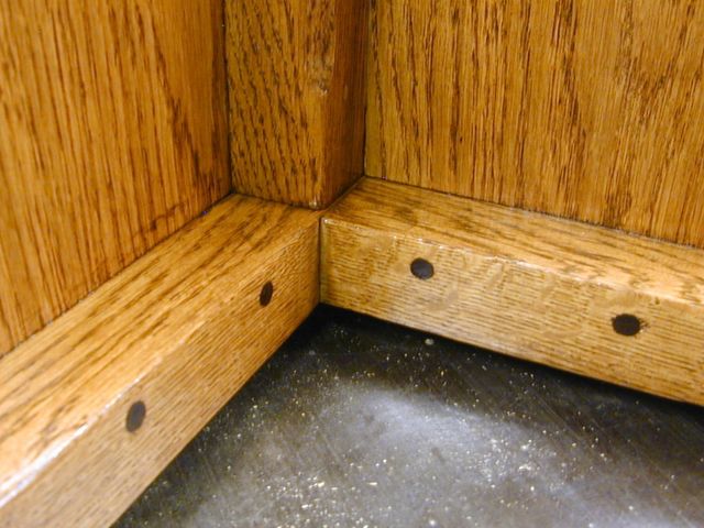
That could be used to consistently place holes through the ends of each segment and the slip tenons. More walnut dowels could be driven though the holes and planed flush to add strength to the joint and some visual appeal
I decided that gluing and clamping up a large octagon would probably be quite tricky. So I figured I could make life much easier if I used the draw bore technique the not only pin the joints, but also pull them firmly together.
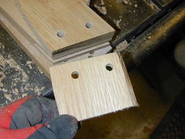
So I started by drilling more holes with the guide in the "open" ends of the segments. To prevent the wood chipping out inside the mortice, a small sacrificial "spelch" block could be inserted for support before each drilling.
Each segment could then be dry fitted, and the brad point frill bit used to make the holes, used as a punch to mark the position where the holes intersect the tenons. Next drill the tenons, but moving the hole position about 1/32" closer to the shoulder of the --- TBC
