Metal handrails for garden steps
Introduction
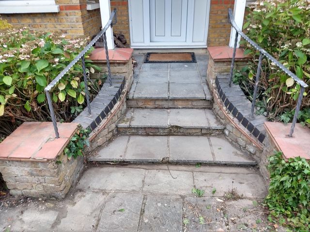
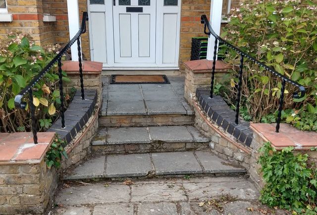
There are three fairly shallow steps up to our front door with a low curved masonry wall to each side. While being generally fairly easy to climb there are no handrails or obvious places to steady yourself, which can be a bit of a problem in the snow and ice or when infirm visitors call. Hence I decided to add some handrails.
Design
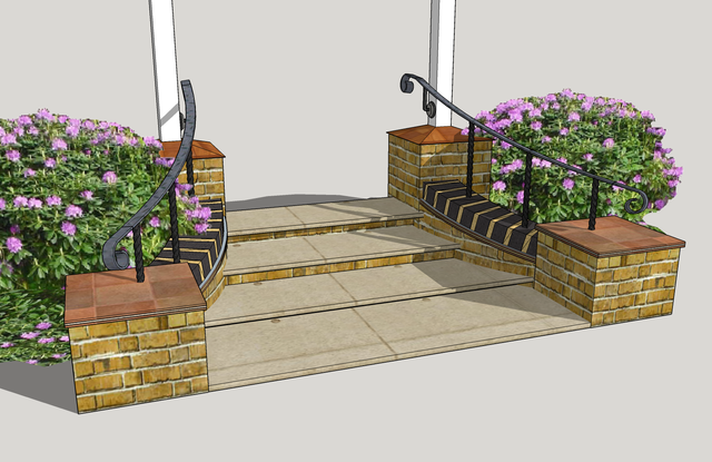
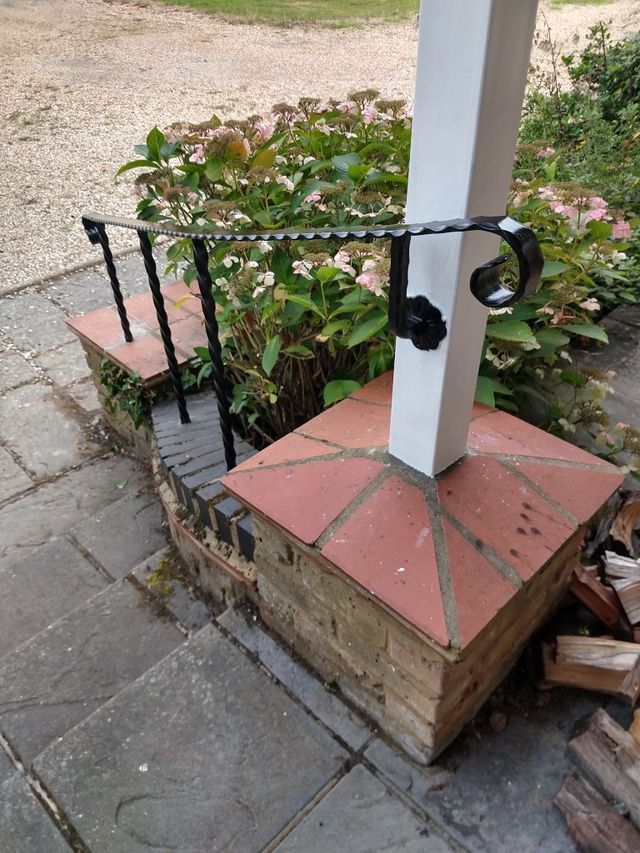
There is already some ornate ironwork elsewhere in the garden, so I decided to go for a functional but slightly ornamented "wrought iron" style design. To keep everything simple, I decided that the top of the rails would start adjacent to an existing pair of square steel posts that form a part of the porch.
The support for the remainder would come from uprights resin bonded into holes drilled into the existing masonry.
The obligatory (not quite to scale) sketchup model:
Materials
For these I ordered 3m of "Heavy hammered" handrail in 40x8mm, 4 matching scroll ends, 6m of 20mm twisted bar, and two ornate brackets. All supplied by F H Brundle who carry a massive array of iron and steel products for pretty much any kind of gate, rail, fence, or balustrade you can imagine.
Construction
Mounting the posts
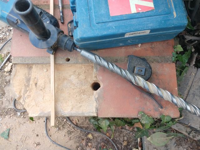
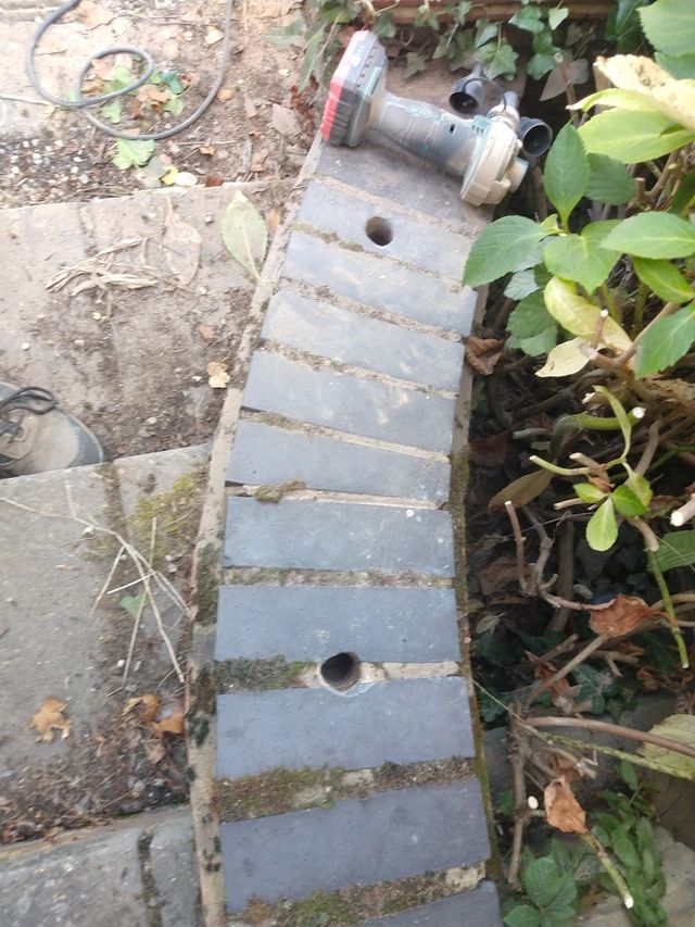
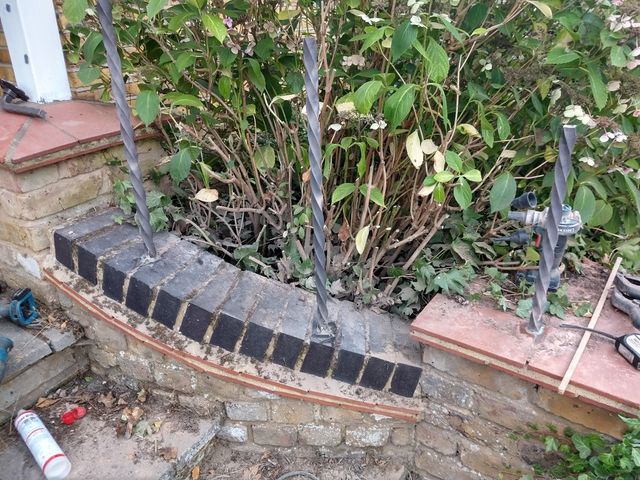
First job was to drill the mounting holes in the masonry for the posts. I did a small test hole in the mortar on the lower plinth, just to see if it was solid or hollow. Alas hollow, so that meant to get a good fixing the holes needed to be over the brickwork at the periphery of the plinth which would mean less space available for the curve in the original design.
Although the posts are only 20mm steel solid square section, they are twisted. That in effect makes them "round" with an effective diameter 28mm because you need to accommodate the corner to corner width of the steel. I had bought a 30mm diameter 450mm long SDS drill bit just for this job.
Now these were "difficult" holes for a number of reasons. Firstly the diameter of the bit means that its quite a substantial mass of metal in its own right. This means that not only do you get reduced impact energy transferred from the drill, you are also drilling with a bit that is not far off the mass of the 2kg class SDS drill itself! So lots of vibration comes back to the operator through the drill as the laws of conservation of momentum do their worst!
It was also difficult since some of the holes were through very hard blue engineering bricks at an angle. So 10 to 15 mins per hole with plenty of rest stops along the way.
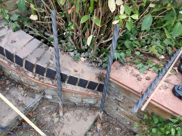
To help drill the holes as close to vertical as possible, I placed a line projecting laser so that it put a vertical line on the drill bit, to give me a frame of reference, but it was mostly by eye and feel of the balance of the drill and keep it upright. Making the hole a few mm oversize not only allows space for the resin, it also gives a bit of alignment wiggle room. So for a couple of posts I could tap a small wedge into the top of the hole to prop the post at the right angle while the resin cured.
Once the holes were drilled, it was time to cut the posts to length (or a bit over length). I allowed a good 8" of extra length to sink into the masonry so that it was fixed into more than one course of bricks.
Now the job of actually fixing the posts. This was done with Fischer VL300T Vinylester Resin. This comes in a typical 330ml mastic cartridge that fits a normal sealant application gun. It's a two part resin that is mixed by a special nozzle after it is ejected from the tube. Generally it is good to work fast and get a few holes bonded at a time since you only have 10 to 15 mins before the resin sets. (you can save a partially used tube for later use, but each nozzle is a "one use only" affair, since it will be full of set resin after the first use. (each tube comes with a pair of nozzles - so if you are buying a few tubes at once, you normally have more than enough nozzles to start and stop as often as required. With larger jobs with lots of fixings, you can just swap your working nozzle to a new tube each time you run out).
(Prior to fixing with the resin, I was wondering how to clear some dust from the holes... then I remembered that years ago a friend had given me a cordless car tyre inflator, that also came with a tool for inflating "blow up" things. The car tyre unit has proved quite handy, but I had never had much use for the inflatables unit. Until now that is, where it turns out to be quite a good blowing tool for clearing dust from holes!)
Fixing the top brackets
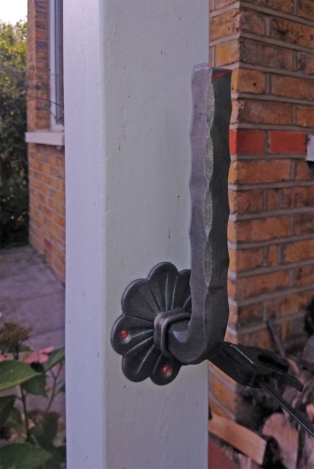
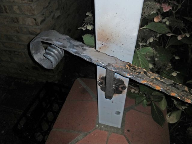
The next job was to get the top bracket fixed to the existing metal post. So the plan was to work out the right height, clamp it in place, and fix it. Since the post is hollow galvanised steel, its not that easy to get a screwed fixing onto it that would not look ugly, so it seemed like it would be easy to plug weld through the supplied fixing holes directly onto the post.
Easy huh? Well I thought so, until I welded it, took my clamp off, and the bracket fell off! It turns out it had filled up the mounting holes nicely, but achieved zero penetration into the post! So I had to drill out the holes in the bracket and try again. On about the third attempt, I found a method that worked well and reliably:
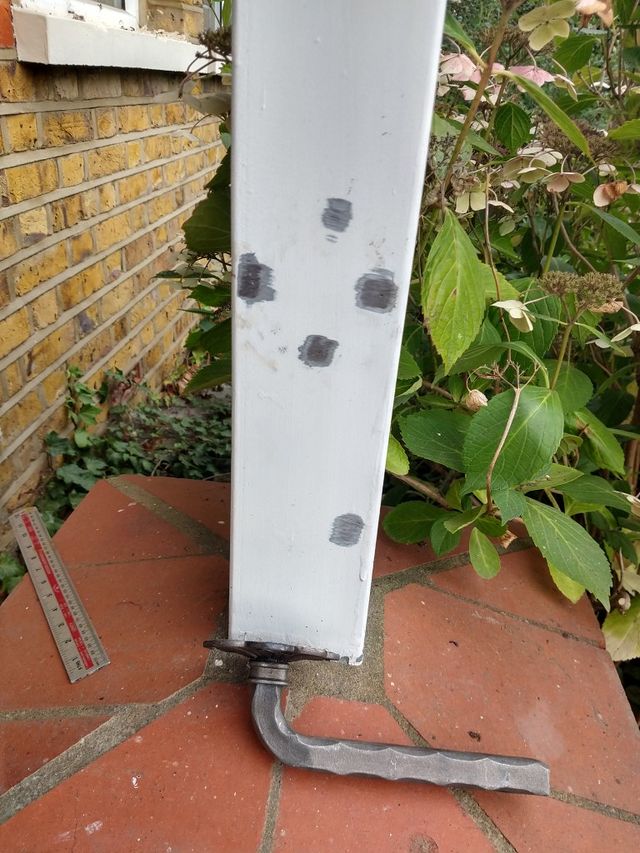
Clamp bracket in place. Use a centre punch to mark the centres on the post. Then remove the bracket and use the centre punch marks to identify where to grind through the paint and galvanisation on the post.
I also ground a place to clamp my earth electrode onto the post to make sure I would get good contact to the post.
Lastly I placed a small tack weld right on each centre punch mark. This made a nice set of nibs to get positive registration on when clamping the bracket to the post. Finally plug welding through the holes onto the existing tacks got a good solid fixing.
Now I had all the mounting points, I needed to work out the exact height, and positioning of the rail, and also trim each post to the right height with the right "slope" on the cut to match the rail.
Shaping and fitting the handrails
I got a thin bendy off-cut of timber and clamped that to the top and bottom posts, bending it round the tops of the middle posts. I fiddled the position about until I had it in what seemed like a good position for the rail. When I was happy with the position of the wood strip I used it to mark the cuts on the posts, before cutting the tops of the posts with the angle grinder.
The strip of wood was also a handy way to measure the exact length of rail required for each side taking into account the curve. That turned out to be 1520mm on the first side. Which rang a small alarm bell since I had only bought a 3m length of rail! However it turns out when measuring the rail as supplied, it was 3040mm, which was quite fortunate. So I cut that exactly in half (with a thin kerf disc!)
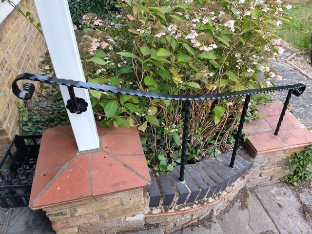
Now I could lay the section of handrail in position on the posts and work out where to bend it. Although I had originally drawn it as being curved for most of its length, in reality most of the lower section was straight, and only one curved section was required toward the top.
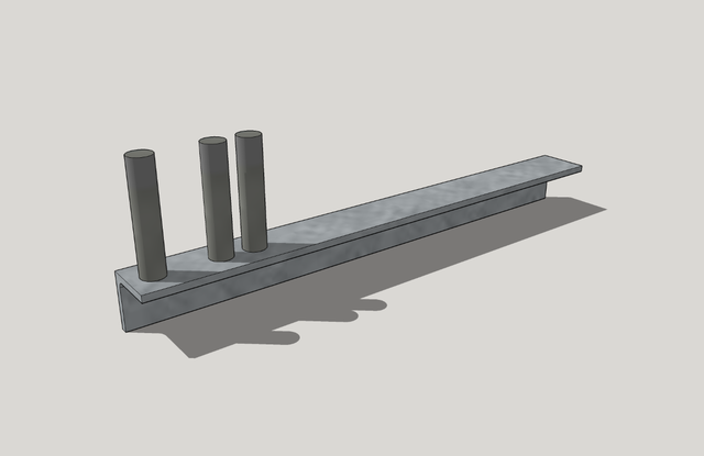
Once slight complication of the design, is that the rails need to be bent (fairly gently) along the wide axis. Not having access to many serious metal working tools like a hydraulic press or a forge, I needed to find an easy way to do this. Some experimentation on a bit of spare flat bar showed that it was quite possible to re-purpose the wood working trick called kerf bending. So this is what I set out to do here. To make that a bit easier, a made up a quick bending jig that I could clamp in a vice. It just consisted of a length of 40x40mm 5mm thick angle, with some 16mm posts welded to it:
The wider set of posts for bending on the wide axis, and the narrower ones for tweaking on the narrow axis.
The jig was made by welding some 70mm lengths of 12mm rebar to the angle iron first, then sliding the 75mm long 16mm diameter steel tube offcuts over those, welding those at the bottom to the angle, and at the top to the rebar to fix them in place.
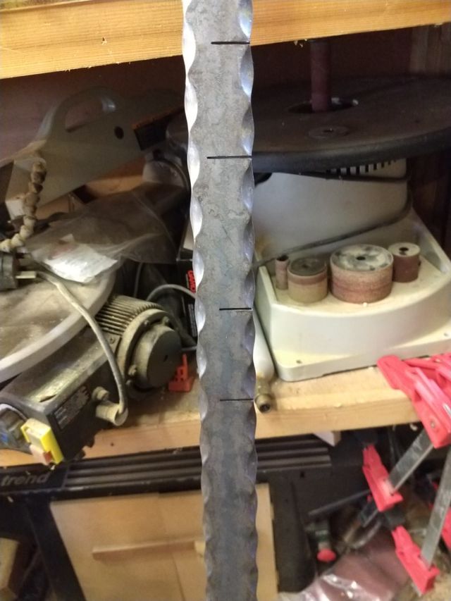
To make the bend possible by manual force alone, I marked up positions for the kerf cuts every couple of inches to match the pattern on the edge of the steel. I cut these with a 1mm slitting disk in the angle grinder:
I bent the rail to shape with the bending jig, and test fitted again. Where I needed a bit more bend I could either add another kerf, or I could recut one of the the original kerfs after it had been closed up by the first bending, thus allowing a bit more room to bend in that section.
After two or three trips to the workshop I managed to get a nice bend in the rail that let it meet all the posts, and left the top of the steps with a parallel section of rail that was perpendicular to the steel posts.
Fixing the rail
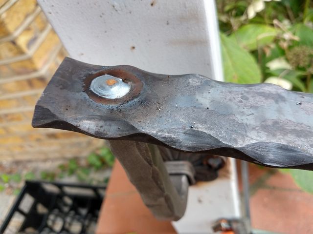
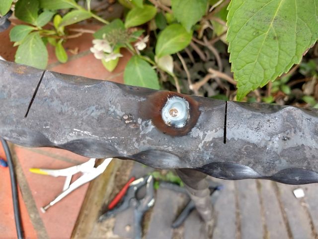
To hide the weld that would fix the rail to the post, I drilled a 12mm hole through the top of the rail exactly in line with where the post met the rail, and then "plug" welded down into this hole to join the top of the post to the rail, while filling the hole with weld. At the top:
Further down:
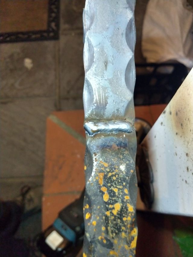
When all the welds to the posts were done, I could then set about welding up the kerfs. Rather than simply weld over them as I had on my trial, I used a grinding disk on the angle grinder to "vee out" each kerf to create some extra depth in the top of each cut. This allowed for a deeper more penetrating weld that filled most of the cut right through the rail.
Once all the welding was done, I then ground the visible welds flat with a 40 grit flap disc.
That got most of the basic fabrication done. However I did not yet have the scroll ends since these were on backorder. So to prepare for these I just bevelled the ends of the rail at approx 45 degrees.
One side:
Both together:
Fixing the scrolls
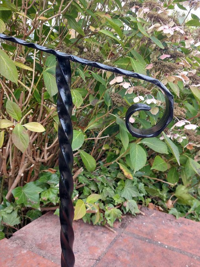
This was a quick and easy job. The scrolls were supplied with a 400mm length of rail, which was more than I needed, so I cut these down a bit with a 45 degree bevel cut. I tried to match the pattern (with varying degrees of success) so that it would flow into that on the existing rail. By having full depth bevels on both the rail and the scroll, I could join the parts with a full depth weld.
I clamped an off-cut from the scroll ends under both bits before welding to make sure that the scroll sections were square both side to side and up and down.
A quick lick with the flap disc made that look pretty:
Painting
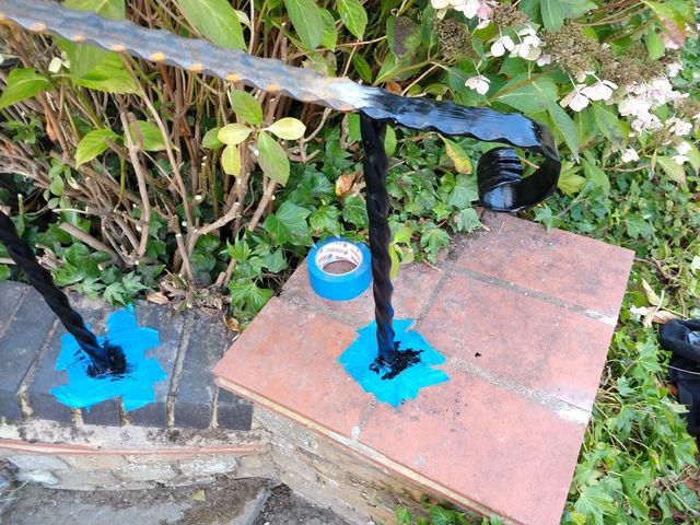
The last job was to make it all look pretty, so I masked up, and set about the rails with some smooth black Hammerite.
It was only when getting down low to mask up for the painting, I noticed that some of the joints to the rail did not match the rail angle perfectly (down to my not cutting exactly the right angle on the top of the posts), thus leaving a small gap. Rather than risk water being able to get into the joint here, I touched up the weld from below to fill in any gaps before painting.
There was a bit of a knack to finding the right brush angle for the twisted section, but it was quite easy to paint.
Once the rail and posts had a first coat and dried, I de-nibbed with some 120 sandpaper, and used two part filler to fill any pits or hollows that were visible, and sanded that flush before giving it another coat.
I also repainted some of the white on the posts to repair any scratches and remove any discolouration left from welding.
and the other side:
The scroll detail:
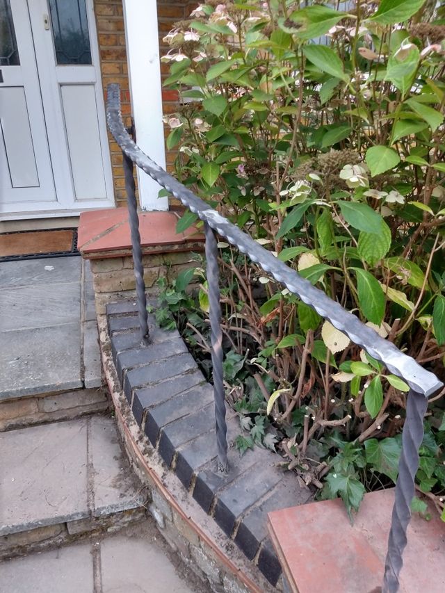
Finished result:
The final job was to patch up the mortar on the tiled plinth at the bottom of the steps, re-fixing the tile that came lose when drilling, and fixing the pre-existing broken corner on the left plinth. Hopefully when that mortar has weathered in a bit it will look less obvious.
Conclusion
Total materials bill was around £115 for the steel, £30 for the resin, and £8 for paint. Add in a few cut off disks and other sundries like MiG wire and gas, and a cheap £10 drill bit.
See Also
Tried a prettier version on some other steps.
