Difference between revisions of "Power factor"
m (extra intro, and section on relevance to DIY) |
(→Other causes of low power factor: - better wording on harmincs) |
||
| Line 154: | Line 154: | ||
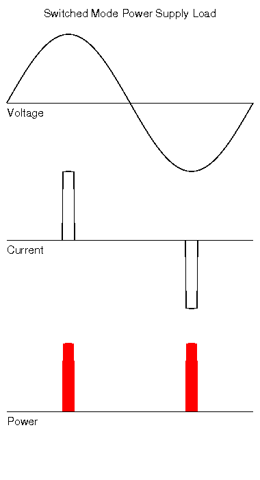
Switched Mode Power Supplies (SMPS) typically rectify the mains and use this rectified AC to charge a capacitor. The capacitor is then in turn used to power the later parts of the power supply circuit. Each mains cycle the capacitor it "topped up", but this can only happen when the mains potential is above that of the capacitor, which means this has the effect of only drawing current near the peaks of the mains voltage, and none at all during the remainder. | Switched Mode Power Supplies (SMPS) typically rectify the mains and use this rectified AC to charge a capacitor. The capacitor is then in turn used to power the later parts of the power supply circuit. Each mains cycle the capacitor it "topped up", but this can only happen when the mains potential is above that of the capacitor, which means this has the effect of only drawing current near the peaks of the mains voltage, and none at all during the remainder. | ||
| − | Unlike in the examples shown above, there is no phase shift visible between the voltage and current waveforms, the current waveform is '''distorted''' into a square shape and is no longer the same shape as the voltage waveform. This change in shape also means that the current waveform is no longer a | + | Unlike in the examples shown above, there is no phase shift visible between the voltage and current waveforms, the current waveform is '''distorted''' into a square shape and is no longer the same shape as the voltage waveform. This change in shape also means that the current waveform is no longer made up from just a single frequency, but is in now made from a single fundamental frequency with a whole bunch of other frequencies mixed in with it. |
| + | |||
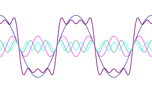
| + | The following diagram shows how a single pure frequency will be distorted as you add in harmonic components: | ||
[[Image:HarmonicWaves.png]] | [[Image:HarmonicWaves.png]] | ||
| + | |||
| + | The blue line represents the main fundamental frequency. All the other smaller waveforms are harmonics (i.e. multiples of the fundamental frequency). If these are all added together, you get the resulting square looking purple wave. The more harmonic frequencies we add in, the cleaner looking the square wave will become. | ||
The actual power dissipated by the load is no longer a simple product of Voltage and Current (since when dealing with AC, this calculation has the implicit assumption that the waveforms are both the same shape). | The actual power dissipated by the load is no longer a simple product of Voltage and Current (since when dealing with AC, this calculation has the implicit assumption that the waveforms are both the same shape). | ||
Revision as of 22:58, 5 March 2010
What is Power Factor
This is quite a "deep" subject when you get into all the detail, so this article will attempt to just cover some of the basics. Power factor (PF) is a concept that only applies to electrical loads being powered from an AC supply. It quantifies what proportion of the apparent power flowing into a load, is actually dissipated as real power.
What is the relevance of this to DIY?
Although power factor is a fairly complex subject to do with technical detail, there are occasions where it may crop up in a DIY setting. The most common cases when designing circuits, and when taking electrical measurements. In circuit design, a low power factor may mean that higher than expected currents will flow, and hence larger cable conductors sizes will be needed. When attempting to measure current flow or voltage drop, a low power factor may result in you getting erroneous readings, as it may fool many test meters.
Reactive power
With a DC supply, the power dissipated by a load is proportional to its resistance and the voltage applied to it. We have some simple relationships that we can apply.
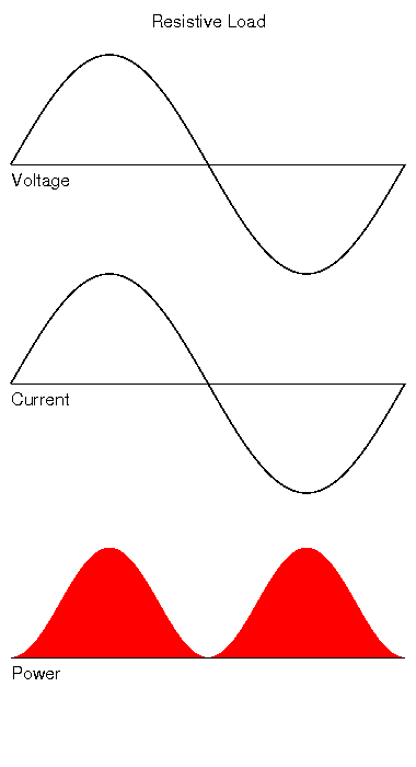
In the simplest cases, the same calculations also apply to loads being powered from an AC source (like the mains). A resistive load being driven from the mains, will draw current that is in sympathy with the mains voltage; as it rises, the current will rise, and as it falls it will fall. At the zero crossing point it will be zero.
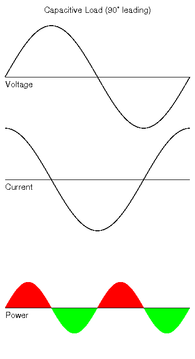
However things can get more complicated due to the effect of "reactive" elements in the load. These are typically components that have an inductance or capacitance. Inductors and capacitors actually store electrical energy (although in different ways). As you might imagine, having something that stores energy being fed from an AC supply, will cause it to charge and discharge in response to the ever changing applied voltage. So during one part of the mains cycle it can be "absorbing" energy, while in another it gives the stored energy back again. Reactive elements in a load can make the types of calculations that are easy to apply to simple resistive loads somewhat more difficult, because you can no longer assume that the current drawn will align with the alternating voltage.
Capacitive load
Inductive load
A similar situation exists with an "Inductive" load. Although inductors store energy like capacitors, they do so in a magnetic field around a coil of wire. Since the wire is coiled, the magnetic field produced by the current flowing in the wire will also interact with adjacent coils. As the current flowing through the coil changes, the associated magnetic field changes. This changing field will induce a current flow in the wire. However the induced current flow caused by the changing field, is in the opposite direction to the flow in the circuit. So the inductor tries to oppose changes in current flowing through it, by counteracting them using its stored energy. This means inductors will offer a low resistance path to stable voltages, but increase their resistance to changing ones - the opposite of a capacitor.
The main difference resulting from this is that the current waveform lags the voltage waveform rather than leads it. (see diagram to the right)
How is a power factor expressed?
A power factor is expressed as a number between 0 and 1. A power factor of 1 (aka a "unity power factor") basically says the power in a load can be treated like a normal resistive load, and ohms law applies. A PF of 0 is a perfect reactive load, or one that actually dissipates no real power at all.
The power factor of our load can be expressed as:
                 Real Power
Power Factor = --------------
                    VA

So in our capacitive and inductive examples above, the power factor
would actually be zero.
A load like this that is totally "reactive" would be unusual. In real world situations, loads can have both resistive and reactive components (and of those reactive components, the capacitive ones will have leading, and the inductive ones lagging phase shifts).
To compute the actual current flow into a load like this at any given time therefore requires "vector" arithmetic to take into account not only the reactance of the leading and lagging components, but also their phase shifts.
Composite loads
In the real world, electrical loads are rarely just reactive, they are usually combined with a resistive element as well. This can give rise to the situation where there is a misalignment between the alternating voltage and the current drawn as before, but not as pronounced. If you look at the resulting power graph, you can see that in this example, most of the power flowing into the load is power transfer that is doing some useful work, but a small proportion is being returned as reactive power.
An appliance like an electric fan heater may present a load like this. The bulk of the current drawn will be supplying the resistive heater element. However a small amount will be driving the fan typically driven by an induction motor.
Other causes of low power factor
The above examples show the classical cause of non unity power factors. A typical real word example of a load that has a less than unity power factor as a result of these phase shift effects is an induction motor. Here a significant proportion of the current flow into the motor is actually reactive and does not get dissipated as work. So a power factor of 0.5 would not be uncommon. Standard linear strip lights are another common load with a poor PF.
There are other causes of low power factor. One such example is where current only flows in the load during some but not all of the mains cycle. giving rise to a non sinusoidal current waveform.
Can you change or compensate for a poor power factor?
Yes, you can do what it called power factor correction (PFC). In the case of poor PFs caused by current phase shifts, you can add other reactive components to the load to try and offset the effects of the reactive components in the load. So if you had a reactive bank of fluorescent strip lights (which have an lagging power factor due to their inductive ballasts), adding a capacitor to create a leading reactive element can actually cancel out the effects of the inductors.
While this is worthwhile in an industrial setting where customers are usually charged based on their VA loading rather than their real power loading in watts, it is far less useful in a domestic one where the meter will give a reasonable indication of the actual power consumption regardless of the PF.
- Note that recent EU legislation has stipulated that larger SMPS (i.e. over 25W) must now include PFC. However there will me lots of legacy equipment in use that does not include this for some considerable time.
Does a low power factor mean I am using more electricity?
Sort of. In the sense you will be drawing more current that you would with a high PF. However in a domestic situation a poor power factor will not result in you being charged for more electricity.
Poor power factors are bad for distribution efficiency though, and can result in the mains supply waveform getting misshapen and noisy - so power supply companies tend to penalise big industrial users if they don't control their power factors.
If you want an analogy, imagine riding a bike up hill. You stick a certain about of push into the pedals to keep it moving overcoming resistance, and more to add the energy you are acquiring by climbing the hill. Imagine someone attaching a big spring to one pedal and the seat post, such that every time you push the right pedal down you also need to stretch the spring. As you can imagine this will take more "push" from you to keep riding. However that extra push is only required on the right pedal. When you push the left pedal you have the energy stored in the spring pulling up on the right pedal and hence working for you. So the result is the bike is harder to ride, but the total energy required to get up the hill is actually the same. This is similar to the effect of having a poor power factor as a result of large reactive elements in the load - the load still dissipates the same amount of energy, but it is harder to drive (i.e. needs more peak current flow).
What about this device that claims to save money?
For industrial users of electricity, PFC can and does save them money. This has lead to some makers of gadgets and gizmos to promote them to domestic customers for the same reason. Alas, PFC alone is unlikely to save you much if anything in electricity, since the standard UK electric meters are actually very good at only measuring the real power used, and not being fooled by reactive currents that may also be drawn from (and returned to!) the supply.
See also
- For a very comprehensive explanation of this topic, I recommend this site.
- Category: Electrical
- Category: Appliances
- Wikipeadia article


