Structured wiring system
A structured wiring system is a flexible and expandable way of installing telecommunications and computer networking capabilities into a home or office. Once the domain of commercial and office installations, there are now many good reasons for installing a system in the average home. This article describes the basics.
What can I do with it?
A structured cabling system will allow you to reliably interconnect computer and telephone equipment around your home. You can:
- share files, folders, printers, and your internet connection between your various computers.
- Install telephones where you need them
- Stream audio and video files to TVs or computers
- Centralise computer backup facilities
Unlike a series of hard wired phone sockets or network points, structured wiring is designed to be flexible. You can decide how you will use each point after you have installed it, and you can change the use later without needing to make wiring alterations.
Why Cable?
In these days of cordless DECT phones, WiFi and HomePlug ethernet you might wonder why it is worth going to the effort to cable a house. However there are a number of advantages. A well installed system gives high reliability - phone calls without drop outs or interference, reliable high speed computer and audio/video appliance communications at gigabit speeds in any building for very low cost, and freedom from the security worries that come with broadcast data comms technologies.
How does it work
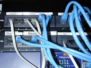
Structured wiring systems can vary from very simple to quite complex. The main difference is one of scale. There are several layers within a large system, including backbone cabling (i.e. cables between central hubs, and hubs / server rooms), "Entrance" cabling - i.e. getting external services like phone and data links into the central hubs etc. However for this article we will concentrated on the bit of it that is most likely to be of interest in a domestic or small commercial setting; the so called "horizontal cabling" where a central hub fans out to individual work locations. The basic design of this part of the system is a "star" type topology. Low cost CAT5e or similar twisted pair cables are run from a central location to each room where they may be required. Each of them are then terminated at a standard modular RJ45 socket. At the central location all of the wires are terminated at a bank of sockets on a "patch panel".
This is simply a row of individual sockets housed in a single module.
At this stage all you have is a pair of sockets joined "back to back" - one in your room, and one connected to it at your hub. What function a particular wire will perform is chosen by how you "patch" it. A patch is simply a short lead that is used to connect the socket to the service of your choice - say a telephone line or a PABX extension line, or a network switch. In the room you can then plug in your network or telephone equipment. If later you decide you need to change a phone point to a data point of move a service from one room to another, all that is typically required is a change at your patch panel to reassign the socket.
Design
It is worth spending some time on your design, since the materials are cheap, but the disruption and time taken to get it all installed is better only endured once!
- Select a suitable location for your communications hub. Something like an under stairs cupboard is often ideal. You want a location that is easy to wire to and from, and has (or can be given) power and light.
- Decide all the places in the house where you may want to install a phone, computer, or AV equipment like hard drive recorders, satellite boxes or TVs.
- For each location, allocate at least two cables (always run a minimum of a pair!). If you expect the location will have lots of equipment concentrated close to it, then allocate more cables.
- Count up how many cables you have and select patch panel(s) with enough ways to accommodate all your cables plus a few spare.
- Select a suitable ethernet (and PABX if using one) switch with enough ports to accommodate all the equipment you plan to install.
- Carefully measure the distance from your hub position to each room socket and record these on a list. Allow enough spare cable to have an extra 1 - 1.5 metres at the hub end, and an extra metre at the wall socket ends.
- Add up all the lengths and decide how much cable to buy. To make installation easy it is better to always have a minimum of two reels of cable. For structured wiring such as this, make sure you buy solid core cable and not stranded (in fact solid core can be used to make free leads as well if required - as long as they are not going to be flexed continually).
When deciding on cable runs try to avoid routes that run in close proximity to mains wiring or other possible sources of interference.
Implementation
Materials
You will need:
- Cable (lots of)
- Patch panel(s)
- RJ45 Modular sockets
- Modular face plates
- Suitable pattress or back boxes for the face plates
- Network switch
- Optional PABX
- Optional Comms Cabinet
- Patch leads (Ethernet and possibly telecom)
- Line Adaptor Units (LAUs) for the phones (if required)
When choosing the cable and accessories the fist decision to make is what specification to buy. For a domestic installation the choice is really between CAT5E and CAT6. CAT5e Was designed to support Ethernet speeds up to 1 Gb/sec. It will also handle all the previous standard that work over twisted pair cable such as 10 or 100 Mb/sec.
CAT6 is a higher spec that is certified for use at higher gigabit speeds, and CAT6a will reliably handle 10 Gb/sec.
CAT5e cables and accessories are cheaper and generally fast enough for any current domestic applications. CAT6 may offer some future proofing.
For domestic work it is worth spending a little extra for cable sheathed with a LSOH (Low Smoke Zero Halogen) material since this eliminates many of the toxic fumes that are released should the cable burn in a fire.
A PABX (Private Automated Branch Exchange) is optional but will add flexibility to your phone system - especially if you have more than one line. Any phone can then handle calls for any line, and yet retain privacy (someone picking up another extension won't be connected to the call). A PABX is also a handy way to integrate Voice Over IP (VoIP). This can be a very low cost way of adding additional lines to your phone system and also reducing you call costs - especially if you make many international calls or have daughters / mother in law etc.
Patch leads are rarely worth making yourself since if you shop around they can be bought tested and ready to go for pennies each.
Preparing Cables
In many cases it will be simpler to install the cables in "looms" i.e. bunches of pre-cut cables that are to follow a particular route. That way a large number of cables can be pulled in one go. This is an effective way to retrofit structured wiring. If you are installing during a build or renovation process, then you may find it easier to pull in individual pairs of wires as you go.
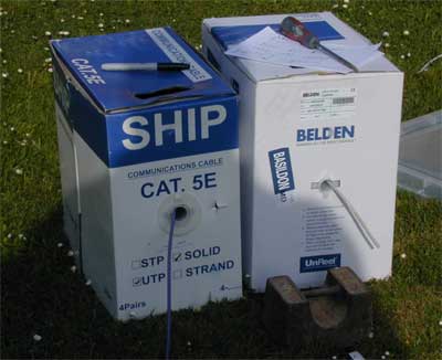
Start by preparing a cutting list. Find some open space, and lay out a tape measure. Since you will be running cables in pairs it is much simpler to have a pair of cable reels to work from:
(and it often helps to use different colours. That way it is clear which cable of a pair you are dealing with at any socket location.
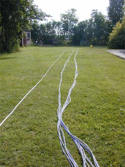
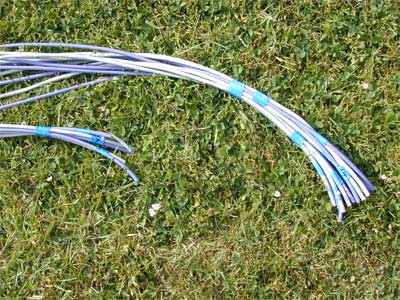
Drag out a pair of cables to the length of your longest pair in the loom. Then tape them together at intervals of every metre or so, plus at each end. Finally use a permanent marker or some other system to label each end. The repeat for the next shortest pair and so on. Once you have a group of cables you can also tape them together to make the bunch more manageable. If you have the space and a long tape measure then this is quite easy to do:
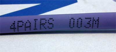
If you don't have as much space and need to coil the cables soon after cutting, or you don't have a long enough tape measure, then use the length markers printed every metre on the side of the cable:
Once you have all the cables for a particular group assembled together and taped up, you can carefully coil them for storage until installation.
Cable Loom Installation
The next task is to install the cables in the house. Many of the techniques described in the Electrical Installation article can be used for guidance on doing this.
Sockets
The next stage is that of installing all the sockets and patch panels. Not a difficult task, but it can get repetitive! Sometimes it helps to get all the socket box mounting done first so that you can concentrate on the actual wiring all in one go.
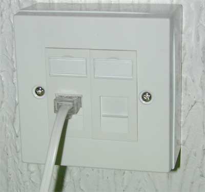
Room terminals can be either small single accessory modular faceplates:
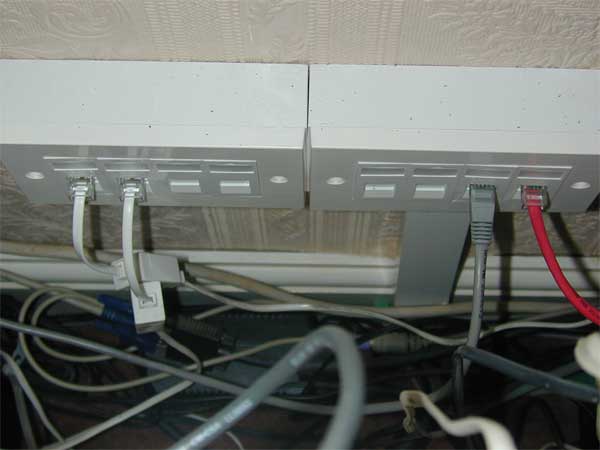
that take a pair of sockets side by side, or for rooms requiring more connections use wide multiway connections:
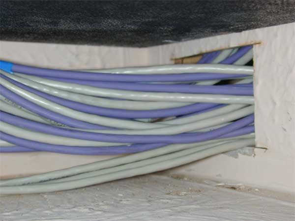
All the cables from the sockets around the house return to the central comms hub in a series of bundles:
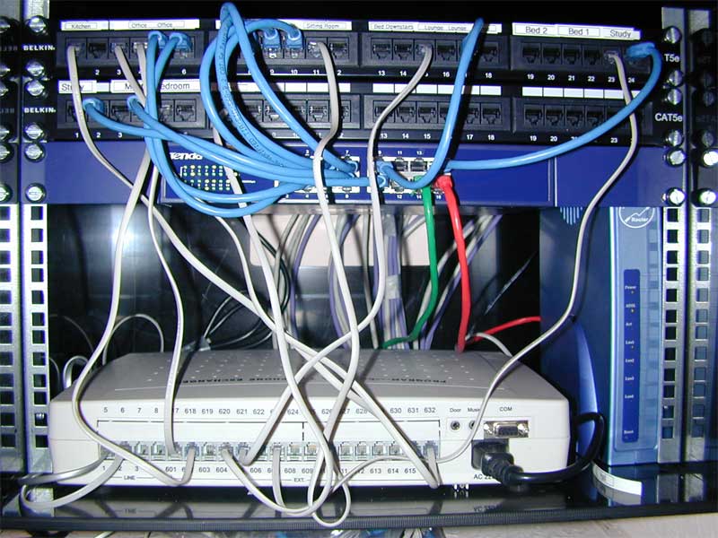
At the hub end it often helps to install a small comms cabinet to keep everything together and tidy:
(the picture shows a 7U wall cabinet containing a pair of 24 port patch panels at the top, a 16 port gigabit ethernet switch, a ADSL broadband router, and a 4/16 port PABX)
Cabinet sizes are specified in "Units" or simply "U". One unit is typically the smallest height device that you would install in a cabinet. Each of the patch panels and the ethernet switch shown above are 1U high - the PABX is more like 1.5U - but is not designed as a rack mount unit and hence sits on the cabinet base rather than being mounted on the front rails.
If you wish to install much equipment not designed for rack mounting, then you can place it on rack mounting shelves.
Wiring Up
Modern datacomms wiring is all designed to be assembled with the minimum of fuss using insulation displacement connector "punch down" terminations. The outer sheath is stripped from the cable and the inner wires are laid into the corresponding colour coded terminals of the socket. Finally a "Krone" type punch-down tool will push the wire into the terminal. The better tools will also trim the wire to length in the same action. There is no need to strip the insulation from the individual wires since the socket terminals are designed to cut through it and make the connection.
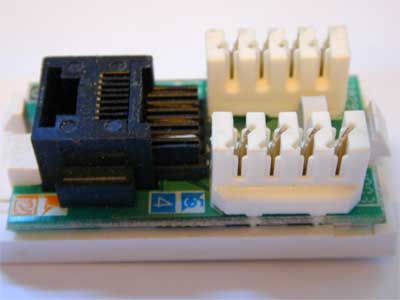
(a typical RJ45 module before it is wired or mounted into the modular face plate)
If you are wiring a few, it is well worth investing in a good quality tool since it will not only work better and faster, it will also usually have some nice extras like a small hook tool for pulling wires free when you accidentally punch them down to the wrong terminal!
A cable stripper is also very handy. These remove the outer insulation from this type of cable with no effort and no risk of damage to the inner cores.
When wiring, most sockets provide a place to allow a cable tie to be fixed - and thus hold the cable to the sockets. Fit this first. and then terminate the individual wires. Make sure you get the right wires in the right terminals. Its not enough that the end to end connections are ok, the actual wires used must be arranged in the right order such that the pairs are kept together for each function. Just to add a little complexity there are several standards for the wire arrangements. The most common ones being refereed to as EIA 568A, and 568B. Which you actually use does not make much difference - but make sure to use the same at both ends of the cable otherwise things won't work correctly. Where possible use the same standard for the whole installation.
Each pair of wires in a CAT5 cable is twisted together. This is fundamental to the way the cable performs when carrying high speed data. It is good practice only untwist as much as necessary when terminating each pair. This helps maintain the noise immunity of the cable.
When wiring the patch panel, it helps to wire each of your numbered bundles in sequence to make keeping track of which lead goes where more manageable!
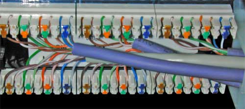
The above photo shows the rear of a six socket section of a patch panel. Each RJ45 socket connects to one block of eight punch down terminals (usually the patch panel contains a PCB that routes the connection between each PCB mounting socket and the punch down terminal block)
Labelling
When complete you can either label the patch panel with the names of the locations of the remote sockets, or simply number each port with a unique number that is matched on the wall socket. This will allow you to tie up a particular wall socket with its matching patch socket.
Testing
The final stage is testing. For a small number of sockets, you can test with known working computers / phones etc. However to do the job easily a basic network cable tester is a much better way. These start from about £30 in most electronics supplies catalogues. The tester will identify any errors in your wiring, or any problems resulting from damage done to the cables during installation. Note that not all pairs of a cable are used in each application. Analogue Telephones only use one pair, and 10 - 100 Mbit ethernet only uses 2 pairs. So it may be possible to use a less than perfect cable for the application at hand anyway.
Correcting mistakes
Failures indicated by a network tester can usually be fixed simply by re terminating any failing pairs of wires. The exception to this being when a cable has been physically damaged during installation. In this case you will either need to pull another wire, accept that you will lose a socket at this position, or see if you can salvage some functionality using the working pairs. In many cases you may want a computer and phone point together. Since the phone only requires a single working pair, you can use the damaged cable to provide that. Alternatively you may need two Ethernet points at that location, but only require 100 Mb/sec operation. Since this only requires 2 pairs per connection you should be able to get two working connections from a pair of cables even with some damage. Take care to document any "improvised repairs" that you need to make like this.
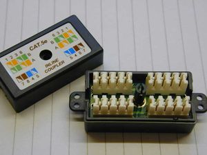
The most common mistake is to find you have cut a cable too short - usually as a result of a need to avoid some unseen obstacle in the fabric of the building. In these cases small punch down junction boxes will allow a reliable connection to be made such that you can graft on an extension.
Use
Using a structured wiring system is simplicity itself.
Data
Connect your ethernet device directly to the socket at the far end using an ethernet RJ45 to RJ45 flylead of appropriate length (make sure it is the flexible type, not the stiffer solid core cable designed for the fixed sections of wiring).
At the hub end connect the ethernet switch to the patch panel via a short network patch lead with a RJ45 connector on each end. For very small instillations it might be appropriate to use the small 4 way switch built into some broadband routers rather than a separate network switch.
Telecoms
With structured caballing, analogue telephone connections typically only use one pair of wires. This is different from the typical UK method of installing hard wired phone sockets that uses three wires. It nicely avoids one of the normal problems that can occur with UK based phone wiring, where the third unbalanced wire (the so called "bell" wire) can pick up unwanted noise and hum as it is routed between each of the sockets.
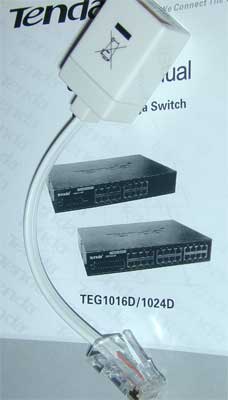
With a structured system, the bell wire is only recreated at the point of use, using a plug in device called a Line Adaptor Unit (LAU)
These adapt the RJ45 socket to take the normal BT style plug on your phone, and also include a ring capacitor to provide the missing bell wire.
The lead required to patch a connection to a phone socket will vary depending on if you are making a direct connection between a BT telephone socket and a patch socket, or between a PABX and a patch socket.
For direct connection, the standard type of lead used on most ADSL routers or dialup modems is ideal. This has a BT plug on one end, and a RJ11 plug on the other (connecting pins 2 and 5 on the BT plug to the centre pair of pins on the RJ11). The BT plug goes into the standard phone socket, and the RJ11 (being simply a narrower 6 pin version of the RJ45 plug will plug directly into the RJ45 socket on the patch panel.
For a PABX connection a RJ11 to RJ11 lead will probably be required, since many PABX systems will have the extension lines presented as RJ11 sockets.
Audio / Video
It is also possible to send audio and video signals down structured wiring. To do this you will need a pair of "Balun" devices to convert the signals to and from suitable formats for transmission. eBay can often be a source of low cost devices!
The alternative way of getting video down the wire is using a media player device. These typically connect to a TV and a central computer or file store and stream audio and video files from it to the TV. In practice these can be treated exactly as described for data connections above.
Splitting signals
Sometimes it is handy to be able to split a signal and direct it to more than one socket. Say for example when connecting a phone line to a number of locations without the use of a PABX. This can be done simply using some spare patch ways on your patch panel. Simply wire together three spare sockets. They can then be used to split one signal two ways. Note this is only usually of practical use for telecomms use rather than data.
