Surface wiring tips
Sometimes you need to install wiring when there is no easy place to hide it. This article give some tricks and tips on doing surface wiring.
Introduction
Surface wiring is sometimes used because its quick and easy and you don't really care what the result looks like so long as it works. Other times there is no practical alternative, but you will want a reasonable looking result.
Why surface wire
You may be wiring something like a wooden building where there is insufficient wall thickness to bury or "chase in" wires, and there are no natural voids in the building structure in which you can run cables. So the only remaining option is to run the cable on the surface. Other times you may not want to disrupt the fabric of the building - say wiring in a lean to conservatory with a nice old soft brick wall on two sides, but you still need power and lighting. Or you may not want to pierce the Vapour Control Layer andor Insulation.
Types of surface wiring
Clipped direct
This is the most basic option, cable clipped directly onto the surface using cable clips or cleats. Its simple and easy to do, but also a bit ugly, and offers no mechanical protection to the cable.
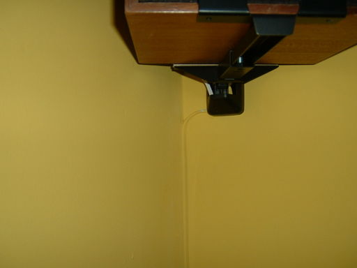
Low-voltage cables such as loudspeakers, telephones and intruder alarm cables are fairly inconspicuous when caulked into the corner of a room and painted over.
In trunking
Can be aesthetically more pleasing in some cases, and a bit neater. Takes more time and effort, but does give some protection to the cables.
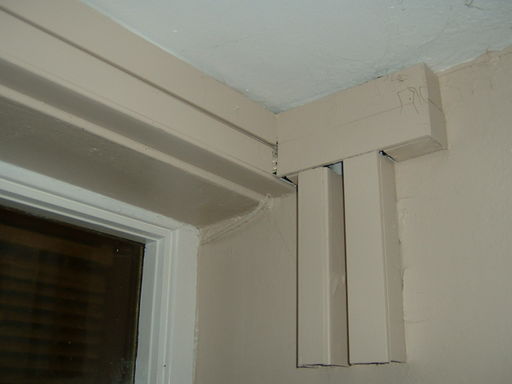
Here sections of 2" x 2" trunking have been used for commual television aerial cables.
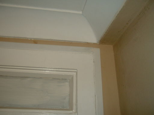
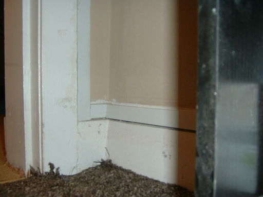
Minitrunking of 16 x 16 mm or 16 x 25 mm is fairly inconspicuous when fitted along architraves and skirtings, and can be caulked and painted to match the woodwork.
Using conduit
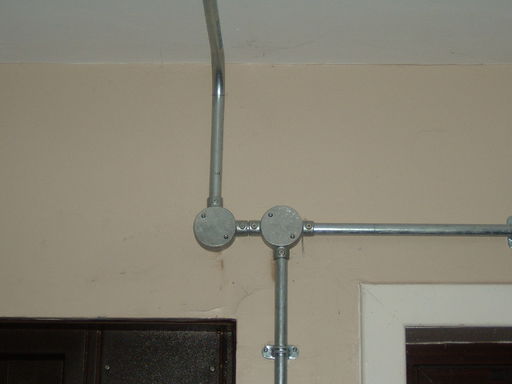
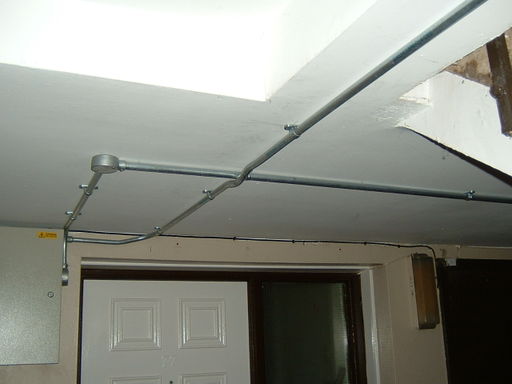
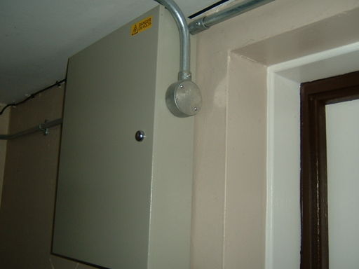
Not unattractive in the right circumstance, and the ideal option for rough service areas. Conduit can range from light through thick wall plastic, onto metal conduit with threaded connections. Much more work to install, but sometimes necessary. Conlok is a steel conduit system with grub-screw couplers, which does not require the conduit to be threaded.
The following installations were for a door entry system in a block of flats, using Conlok conduit:
Using special cables
Cable types like Mineral Insulated Copper Clad (MICC, aka "Pyro") cable can look good in some cases - especially if the copper surface is visible - either left to age and vanish into the background, or polished and lacquered to stand out. The fact that the cable form is very slim also helps. Works well on old brickwork for example.
Less conventional wiring concealment
Although this is not normally considered surface wiring, wiring can be concealed in the building fabric in ways that doesn't involved cutting out walls or using obvious surface wiring methods.
Skirting boards
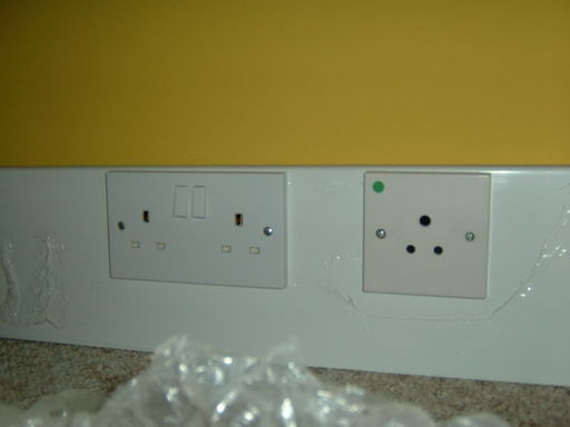
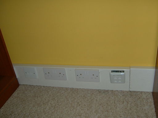
Mains wiring is not permitted to be concealed behind skirting boards, but special skirting trunking can be used as a substitute for wooden skirting. This is particularly useful in buildings with solid floors, such as many blocks of flats, where major expansion of the power wiring is required. The alternative is often to run power wiring in the ceiling and have many drops down to the sockets, which uses more cable and requires a lot of making good.
This skirting was obtained from http://www.kentsdirect.com/ and is sufficient for 2 power rings, 2 lighting control cables, 4 satellite cables, 8 data and 2 telephone cables round the room.
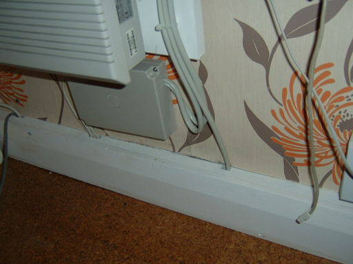
Low voltage wiring may be concealed behind skirting boards. Where there isn't enough room, the skirting may be spaced off the wall with a batten. Some types of skirting include a groove behind for wiring.
Cornicing
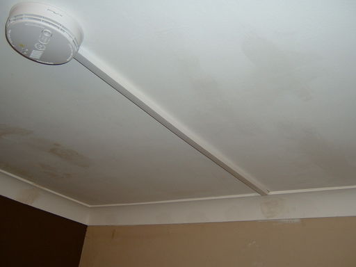
Mains wiring may be concealed behind cornicing, either special cornice trunking or conventional plaster cornicing (as long as the cables are sheathed). This is often useful for getting wiring to smoke detectors without cutting out the ceiling, and cornice wiring is also good for intruder alarm PIR detectors which are usually mounted at cornice level.
Special considerations
On of the difficulties with surface wiring is that some of the common circuit topologies are not as easy to use. For example the classic "loop in" wiring style for lighting requires typically three cables to connect to each lighting position (power in, out, and a switch drop wire). This can make for lots of visible cable. Also there is less opportunity to hide cables, and any junction box will be visible. Hence finding ways to include as many junctions in the accessory enclosures that you need anyway can make for a neater job.
Case studies
Wood constructed outbuilding
This is for summer house. Here there are no building voids, and inadequate wall thickness to sink cables. There is no particular need for much in the way of cable protection, but keeping down the visual clutter is a goal. Hence surface trunking was selected as the method of choice. To look less stark, D-Line trunking was using in a colour that matches the natural wood (the wood will be painted later, so the trunking can be painted to match in the end).
Installation required: there is an incoming power feed that is terminated in a normal double socket mounted on a surface box. To this we needed to add wiring to support an external lamp, under separate PIR controller, with a manual override switch in the building. There was to be an extra double socket. Lighting was to be a central pendant light, and then a pair of lighting sockets for use with table lamps etc but switched remotely from the wall mounted light switch. Lastly there was to be wall mounted downflow fan heater under the control of an external room stat for both heating and frost / damp protection, plus some expansion capability to switch one final set of lights should it be required.
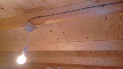
The central light fitting was the easiest one, with a normal ceiling rose. However rather than have lots of cables visible it was decided that running just the already switched supply to the fitting was going to be the most elegant. Since this was overhead and less visible, clipped direct to the side of a roof timber was the chosen option. Once painted it will largely disappear.
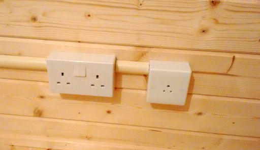
When selecting surface mount boxes, it pays to not use the most shallow available (typically 25mm for sockets). Opting for the deeper 34mm boxes, allows not only more wiring room for the socket itself, but also for additional cables that need to pass through the enclosure that are not actually anything to do with the socket circuit. In the picture above the 2 amp round pin lighting socket is fed from a switched output from the lighting circuit, while the socket is fed from the socket radial circuit. Hence the cable for the second socket must pass through the first without making any connection to it. Arranging the order of the sockets helps such that the 1mm T&E passes through the larger socket backbox, rather than needing the 2.5mm T&E power cable to pass through the smaller one.
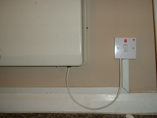
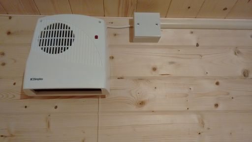
Sometimes you need a place to join a wire or cable, but don't actually need an accessory. In this example a surface box was used to make the transition from the flat T&E cable (switched by a remote stat, in turn fed from a fused connection unit)) to the high temperature butyl rubber flex that feeds the heater. The box is simply blanked off, and conceals some leaver action Wago terminals that joint the flex to the cable.
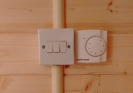
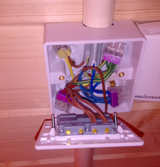
When you can't or don't want to use "loop in" wiring, a light switch mounting box can make the ideal hub for bringing together the various supplies and feeds.
In this example, there is power feed in that is derived from a fused connection unit fed from the incoming power circuit. (on the way it feeds power to the outside lamp and the separate PIR (via some 3&E cable)). There are then two separate output cables to the lighting sockets. A 3&E cable to the room stat. A feed cable to the heater. Lastly another cable to the central pendant light. A triple switch is used so that the lamps and the main light can be switched independently, while keeping a spare switch for future add ons (or it could be re-purposed to allow the lamp sockets to be controlled independently).
That amounts to a fair few cables to deal within one place (4 x 1mm T&E from the top, another at the bottom, and a 1.5mm 3&E to the right). The push wire Wago terminals make for a neat wire joint that does not take up too much space. Crimps are another option, and possibly chockie block style screw connections (although these take more space). The four terminals visible are the common earth point, the common neutral, a common live, and a switched live for the heating. The switched lives for the various lighting feeds are connected directly to the switch terminals.
