Difference between revisions of "Terminating SWA"
m (→Gland Kits: extra detail) |
|||
| (25 intermediate revisions by 8 users not shown) | |||
| Line 1: | Line 1: | ||
| − | |||
| − | |||
| − | |||
| − | |||
| − | |||
| − | |||
| − | |||
| − | |||
| − | |||
| − | |||
| − | |||
Steel Wire Armoured (SWA) cable is a versatile and robust cable ideal for outdoor electrics. However it is difficult to work with due to its size and inflexibility, and also the requirement that all connections must be correctly terminated using appropriate termination glands. This article is a tutorial that shows how to correctly terminate Steel Wire Armoured (SWA) cable. | Steel Wire Armoured (SWA) cable is a versatile and robust cable ideal for outdoor electrics. However it is difficult to work with due to its size and inflexibility, and also the requirement that all connections must be correctly terminated using appropriate termination glands. This article is a tutorial that shows how to correctly terminate Steel Wire Armoured (SWA) cable. | ||
| Line 22: | Line 11: | ||
[[Image:4mmSWA.jpg|4mm² SWA cable]] | [[Image:4mmSWA.jpg|4mm² SWA cable]] | ||
| + | |||
| + | (4mm² is in the small to medium size range of SWA cables typically used in domestic work (1.5mm² being the smallest and 16mm² probably being the largest). Note however all these can be thought of as "small" when compared to the monster sizes used in industry and public power distribution systems such as 400mm² cables with working currents in excess of 600A!) | ||
=Gland Kits= | =Gland Kits= | ||
| − | There are a | + | There are a number of different types of [http://www.tlc-direct.co.uk/Main_Index/Cable_Accessories_Index/Glands_SWA/index.html gland kit] suitable for SWA cable; internal (aka "BW"), external (aka "CW"), and industrial (aka "E1W"). All types will ensure a very rigid fixing of the cable can be made to the box or unit where it connects. and that a good electrical connection can be made to the cable armour wires (used for protective earthing). In the case of the kits designed for outside and industrial installation, they also ensure the connection is waterproof. |
| + | |||
| + | Note that: | ||
| + | |||
| + | *A proper armoured gland kit is the '''only''' acceptable way of terminating SWA when an electrical connection to the armour wires is required (i.e. most cases) | ||
| + | *Using BS 951 type earthing clamps (as used for bonding to water & gas pipes) to connect to the armour is not acceptable | ||
| + | *Taking SWA into an enclosure without the use of any form of gland is also unacceptable since the weight and rigidity of the cable means it must have mechanical support and fixing at entry to an enclosure. | ||
[[Image:3PartSWAGland.jpg]] | [[Image:3PartSWAGland.jpg]] | ||
| − | This is a picture of the seven parts of the somewhat inappropriately named three part gland kit. This is the exterior waterproof style of gland. The interior version lacks the extra gland nut with the rubber insert that is used to seal the the gland against the cable. | + | This is a picture of the seven parts of the somewhat inappropriately named three part gland kit. This is the exterior waterproof style of gland. The interior version lacks the extra gland nut with the rubber insert that is used to seal the the gland against the cable. Beware that the compression ring (the thing that looks a bit like an "olive" in a plumbing fitting) might have an internal taper, and be designed to only fit correctly one way round - look carefully at it when you disassemble your gland. |
| + | |||
| + | ===Gland Sizes=== | ||
| + | Glands come in a range of sizes to suit different sized cables. Each gland will cover a range of cable sizes. Note also that the size of gland required for an exterior / waterproof gland may differ from that specified for an internal gland. Use the following table as a guide, but check the specification of the actual brand of gland you purchase to be sure. | ||
| + | |||
| + | '''For SWA with XLPE Insulation, the following gland sizes are commonly used (note for PVC insulated SWA, the gland size required may be smaller in some cases)''' | ||
| + | |||
| + | {| style="text-align:center" cellspacing="0" cellpadding="6" border="1" | ||
| + | ! | ||
| + | ! colspan="3" |Internal "2 Part" | ||
| + | Glands (BW) | ||
| + | ! colspan="3" |External Waterproof | ||
| + | "3 Part" Glands (CW) | ||
| + | |- | ||
| + | ! rowspan="2" |Conductor area (mm²) | ||
| + | ! colspan="3" |Number of cores | ||
| + | ! colspan="3" |Number of cores | ||
| + | |- | ||
| + | !2 core | ||
| + | !3 core | ||
| + | !4 core | ||
| + | !2 core!!3 core!!4 core | ||
| + | |- | ||
| + | |1.5 | ||
| + | |20S / 16 | ||
| + | |20S / 16 | ||
| + | |20S | ||
| + | |20S / 16||20S / 16||20S | ||
| + | |- | ||
| + | |2.5 | ||
| + | |20S | ||
| + | |20S | ||
| + | |20S | ||
| + | |20S||20S||20S | ||
| + | |- | ||
| + | |4 | ||
| + | |20S | ||
| + | |20S | ||
| + | |20 | ||
| + | |20S||20S||20 | ||
| + | |- | ||
| + | |6 | ||
| + | |20S | ||
| + | |20 | ||
| + | |20 | ||
| + | |20S||20||20 | ||
| + | |- | ||
| + | |10 | ||
| + | |20 | ||
| + | |20 | ||
| + | |25 | ||
| + | |20||20||25 | ||
| + | |- | ||
| + | |16 | ||
| + | |20 | ||
| + | |25 | ||
| + | |25 | ||
| + | |20||25||25 | ||
| + | |- | ||
| + | |25 (shaped) | ||
| + | |25 | ||
| + | |25 | ||
| + | |25 | ||
| + | |25||32||32 | ||
| + | |- | ||
| + | |25 (circular) | ||
| + | |25 | ||
| + | |25 | ||
| + | |32 | ||
| + | |25||32||32 | ||
| + | |} | ||
| + | ''(note that Industrial E1W glands with double seals have been omitted since they are unlikely to be required in a domestic situation, however the sizing requirements are usually the same as for CW glands)'' | ||
=Step 1 - Assemble the gland parts on the wire= | =Step 1 - Assemble the gland parts on the wire= | ||
This task is best done first, since there is nothing more irritating to complete a nice neat termination and then realised you forgot to fit one vital component of the gland on the wire. It also saves having to slide bits over the exposed armour or conductor wires. | This task is best done first, since there is nothing more irritating to complete a nice neat termination and then realised you forgot to fit one vital component of the gland on the wire. It also saves having to slide bits over the exposed armour or conductor wires. | ||
| − | First cut the nose of the plastic boot, such that the hole left will be a snug fit over the outer sheath of the cable | + | First cut the nose of the plastic boot, such that the hole left will be a snug fit over the outer sheath of the cable. The further up the conical section of the boot you cut, the bigger the hole left. Use the cable as guide to the size required. Take it easy and err on the side of caution. If you cut too little off the conical section you can cut more later, but if you cut too much then you may curse your over-zealousness! :-) |
[[Image:ChopBoot.jpg]] | [[Image:ChopBoot.jpg]] | ||
| Line 44: | Line 112: | ||
Note that with some gland kits (especially in the bigger sizes) the fixing ring may be conical to match the cone fitting, and hence must be fitted the right way round. | Note that with some gland kits (especially in the bigger sizes) the fixing ring may be conical to match the cone fitting, and hence must be fitted the right way round. | ||
| − | =Step 2 - Stripping the outer insulation= | + | =Step 2 - Stripping the outer insulation and cutting the amour= |
| − | + | There are a number of options here, which works best for you will depend a bit on the size of the cable and the tools you have to hand. | |
| + | |||
| + | You will need to strip the cable down in layers - keeping different layers at different points. At the end you will need the inner wires free from outer sheath, armour wires and inner bedding. Further up the cable you will normally strip the outer and armour but leave some bedding, and finally to make the connection to the gland you will need a short section of cable with just the outer sheath removed, but with enough armour still in place (with the smaller glands, you need about 30 - 40mm of free armour to fit over the cone section of the gland). | ||
| + | |||
| + | ==Stripping just the outer== | ||
| − | + | Stripping the outer sheath on its own is quite easy. Simply ring the cable at the point you want to strip from: | |
| − | + | '''Quick definition:''' | |
| + | |||
| + | Ringing: Rotating the cable against the knife blade, applying pressure with your thumb | ||
| + | to the other side of the cable. Thus cutting through the outer insulation. When the armour | ||
| + | is in place you can be quite firm here since the armour will protect the cable from any | ||
| + | damage (but you will blunt your knife a little!): | ||
| + | |||
| + | [[Image:RingOuter.jpg]] | ||
| + | |||
| + | |||
| + | Then slice down the outer as shown below to remove the outer insulation from your ring cut to the end of the cable: | ||
[[Image:SliceDownOuter.jpg]] | [[Image:SliceDownOuter.jpg]] | ||
| − | + | ||
| + | ==Cutting the armour== | ||
| + | |||
| + | Most approaches to cutting the armour are actually easier to do through the outer sheath, since while this is in place it stops the wires from moving about as you try to work them. | ||
| + | |||
| + | The "standard" approach is to work out where you will want the armour wires to end, and use a small hacksaw to cut a ring around the circumference of the cable, through the outer insulation, and about half way through the armour as you go. Once you have stripped the outer sheath as described above, you should then be able to break off each of the wires at the partly cut section with a quick wiggle of each wire. | ||
| + | |||
| + | Finally ring the outer insulation a little further up the cable to expose some of the armour ready for gland fitting. This method works well on the bigger cables. | ||
| + | |||
| + | A variation on this technique that works well for cables of up to about 10mm² is to cut the outer insulation and part cut the armour wires using a regular plumbing style pipe cutter as you would use for copper pipe. You can use the pipe cutter to not only ring the outermost layer of insulation, you can also use it to accurately cut the outer and part cut the armoured wires. Again once you have part cut the wires with the pipe cutter, removing the end bit of outer insulation and wiggling the wire will cause them to break off at the "nick" made by the pipe cutter. (Note that you will need many more turns with the cutter, and more clamping pressure than you would usually use for a copper pipe since the steel wires are far harder). | ||
| + | |||
| + | Purpose made tools such as the [http://www.tlc-direct.co.uk/Products/KTWSBR28.html Blade Runner] are perhaps the easiest and fastest way to prepare the armour wires. These work in the same way as the pipe cutter, only using a segment of hacksaw blade to do the cutting. This works very much more quickly than a standard pipe cutter. | ||
| + | |||
| + | For the smallest cables, you may find it as quick to start by ringing the outer sheath at the final sheath position, and remove all the outer insulation from there to the end of the wire leaving the armour wires exposed at their full length: | ||
[[Image:PartStripped4mmSWA.jpg]] | [[Image:PartStripped4mmSWA.jpg]] | ||
| − | + | You can now trim the armour to length. Mark the cut position with a soft pencil (or ring the cable again with the knife to leave a mark on the wires), and then use a strong pair of side cutters to snip off the wires a few at a time: | |
| − | |||
| − | |||
| − | |||
[[Image:SnipArmourWires.jpg]] | [[Image:SnipArmourWires.jpg]] | ||
| − | Try to get the wires about the same length all round. | + | Try to get the armour wires about the same length all round. This only works on the smaller cables since the armour wires on the larger ones get difficult to cut like this. However it is quite quick compared to a hacksaw. |
| − | + | Whichever method you use, when you are done you should now have something looking like this: | |
| − | |||
| − | |||
[[Image:ArmourCut.jpg]] | [[Image:ArmourCut.jpg]] | ||
| − | =Step | + | =Step 3 - Stripping the bedding or inner insulation= |
You don't have to carry out this job now, but it can make the wire end a bit more flexible to work with, so now is as good a time as any. There are a number of ways to do this, and which works best for you will partly depend on the tools you are using and the type of inner insulation your SWA has. The one used in this example has a fairly hard and inflexible insulation that is not easy to tear. So the simplest method is to ring it with a sharp knife as we did for the outer insulation: | You don't have to carry out this job now, but it can make the wire end a bit more flexible to work with, so now is as good a time as any. There are a number of ways to do this, and which works best for you will partly depend on the tools you are using and the type of inner insulation your SWA has. The one used in this example has a fairly hard and inflexible insulation that is not easy to tear. So the simplest method is to ring it with a sharp knife as we did for the outer insulation: | ||
| Line 83: | Line 173: | ||
Once you have broken the insulation all round you can usually slide it off the wires. Using a twisting motion often helps a little. | Once you have broken the insulation all round you can usually slide it off the wires. Using a twisting motion often helps a little. | ||
| − | =Step | + | (in practice it is probably better to leave a little more bedding on than shown in these photographs, so that it protrudes a little from the gland once fitted. This will offer a little more abrasion protection to the insulation on the conductors) |
| + | |||
| + | =Step 4 - fitting the gland cone section= | ||
The cone section of the gland needs to slide between the inner insulation of the cable and under all the armour wires. To make this easy to do you need to splay the wires out a little first. One way to do this is the hold the cable in one hand, and the inner section of the cable in the other, and pull it to one side bending some of the amour wires out where they leave the outer sheath. Now move the inner round in an "orbiting" motion, so as to splay out all the wires: | The cone section of the gland needs to slide between the inner insulation of the cable and under all the armour wires. To make this easy to do you need to splay the wires out a little first. One way to do this is the hold the cable in one hand, and the inner section of the cable in the other, and pull it to one side bending some of the amour wires out where they leave the outer sheath. Now move the inner round in an "orbiting" motion, so as to splay out all the wires: | ||
| Line 100: | Line 192: | ||
[[Image:ArmourClampFixed.jpg]] | [[Image:ArmourClampFixed.jpg]] | ||
| − | =Step | + | =Step 5 - sealing the back of the gland= |
Now the armour is correctly clamped we can fit the cable sealing nut if we have one. This works like a compression fitting and sandwiches the internal rubber sealing sleeve against the outer insulation of the cable making it watertight: | Now the armour is correctly clamped we can fit the cable sealing nut if we have one. This works like a compression fitting and sandwiches the internal rubber sealing sleeve against the outer insulation of the cable making it watertight: | ||
| Line 106: | Line 198: | ||
[[Image:WaterproofingGlandInPlace.jpg]] | [[Image:WaterproofingGlandInPlace.jpg]] | ||
| − | =Step | + | =Step 6 - Connecting to your box= |
| − | Now the gland is fitted to the cable we can attach it to the actual box or panel that the cable is intended to connect to. For the smaller SWAs a 20mm knock out makes | + | Now the gland is fitted to the cable we can attach it to the actual box or panel that the cable is intended to connect to. For the smaller SWAs a 20mm knock out makes an ideal termination hole. Metal boxes often have pre-made holes ready to take SWA and conduit glands. [http://www.tlc-direct.co.uk/Products/LB9065.html Plastic ones] will often need a knockout trimming out with a sharp knife first. |
If you don't have an appropriate sized entry hole, (or you have the sort of hard plastic box that looks like it will shatter as soon as you look at it), then a small 20mm hole saw is ideal for making a suitable hole: | If you don't have an appropriate sized entry hole, (or you have the sort of hard plastic box that looks like it will shatter as soon as you look at it), then a small 20mm hole saw is ideal for making a suitable hole: | ||
| Line 113: | Line 205: | ||
[[Image:20mmHolesaw.jpg]] | [[Image:20mmHolesaw.jpg]] | ||
| − | For this example we will terminate the gland on a standard metal box: | + | For this example we will terminate the gland on a standard metal box (this is a poor example in reality since you would be very unlikely to ever terminate at a flush mounting box like this since the gland assembly will need to remain accessible for maintenance (being a screwed electrical connection) - but it was what was to hand when the camera was poised! A more typical metal box would be one of the surface mounting metal clad types): |
[[Image:Through20mmHole.jpg]] | [[Image:Through20mmHole.jpg]] | ||
| − | To make an effective earth connection to the armour there are a | + | To make an effective earth connection to the armour there are a several ways of doing it. The standard way to do it is using the supplied earth tag (aka "banjo tag") and lock nut. If you need to keep the whole connection within the box then you may need to start by bending the tag a bit: |
[[Image:BendSolderTag.jpg]] | [[Image:BendSolderTag.jpg]] | ||
| − | This will make | + | This will make fixing the earth wire to the tag simpler. Usually bolting your wire (via a suitable crimped terminal) is the easiest way to fix to the tag in the field. You can also solder to it but this is not always easy since there is a fair bit of metalwork to heat. If you do solder to the tag it is better to do it before it is mounted on the gland and in the box. On plastic boxes this will save you melting the plastic, and on metal ones it stops the extra metal conducting all the heat away and making it hard to solder. |
The tag is now clamped between the box wall and the lock nut: | The tag is now clamped between the box wall and the lock nut: | ||
| Line 127: | Line 219: | ||
[[Image:TightenLocknut.jpg]] | [[Image:TightenLocknut.jpg]] | ||
| − | + | To bolt your wire to the tag it is best to crimp a ring terminal to the end of your wire: | |
[[Image:EarthWireWithEyeTerminal.jpg]] | [[Image:EarthWireWithEyeTerminal.jpg]] | ||
| − | and bolt this to | + | In this circumstance it is often better to leave the tag flat, and drill a matching hole in the enclosure that lines up with the terminal hole on the tag. That way you can now bolt right through the tag and the enclosure. If you use a pan headed bolt, with the head on the outside of the box it does not look too untidy either. Note doing this is not recommended for boxes that need to remain completely waterproof. |
A nicer solution however is to dispense with the tag and lock nut altogether, and use one of the proprietary fixing nuts like [http://www.tlc-direct.co.uk/Products/PRPEN20.html this] that act as both lock nut, and also allow eye terminals to be screwed or bolted directly onto the nut. | A nicer solution however is to dispense with the tag and lock nut altogether, and use one of the proprietary fixing nuts like [http://www.tlc-direct.co.uk/Products/PRPEN20.html this] that act as both lock nut, and also allow eye terminals to be screwed or bolted directly onto the nut. | ||
| + | |||
| + | With metal enclosures and boxes it is also acceptable to do away with the tag altogether and just rely on the interface between the gland and the box. If you are doing this it is vital that the mating surfaces of the box are cleaned to ensure no corrosion or paint will interfere with the connection, and also that the back nut is done up tightly. Note also that when the enclosure you are connecting to is to house an accessory (e.g. a socket) to comply with BS7671 [543-02-07], The earthing terminal of the enclosure must also be connected by a separate wire to the earth terminal on the accessory. Particular care is needed if the mounting plate that the gland fixes to is removable, since one may not rely on the screws that hold it as being a good enough earth connection on their own. | ||
The final job is to slide the plastic boot into place, making a nice neat job: | The final job is to slide the plastic boot into place, making a nice neat job: | ||
| Line 145: | Line 239: | ||
=See Also= | =See Also= | ||
| − | * [[Special:Allpages|Wiki Contents]] | + | |
| − | * [[Special:Categories|Wiki Subject Categories]] | + | *[[Special:Allpages|Wiki Contents]] |
| − | * [[Cables]] | + | *[[Special:Categories|Wiki Subject Categories]] |
| − | * [[Taking electricity outside]] | + | *[[Cables]] |
| − | * [[Wiring colour codes]] | + | *[[Taking electricity outside]] |
| − | * [[Electrical Circuit faults#Required Equipment|Cable Resistances]] | + | *[[Wiring colour codes]] |
| + | *[[Electrical Circuit faults#Required Equipment|Cable Resistances]] | ||
=External Links= | =External Links= | ||
| − | |||
| + | *[http://www.basec.org.uk British Approvals Service for Cables (BASEC)] | ||
| + | *[http://www.etscc.co.uk/blog-home/earthing-requirements-cable-glands-swa-cables Earthing Requirements of Cable Glands Used on SWA Cables] | ||
[[Category:Electrical]] | [[Category:Electrical]] | ||
Revision as of 08:01, 28 October 2020
Steel Wire Armoured (SWA) cable is a versatile and robust cable ideal for outdoor electrics. However it is difficult to work with due to its size and inflexibility, and also the requirement that all connections must be correctly terminated using appropriate termination glands. This article is a tutorial that shows how to correctly terminate Steel Wire Armoured (SWA) cable.
Cutting SWA
For the smaller and intermediate sizes of SWA, the quickest way to cut it to length is using a large pair of bolt croppers:

(for very large sizes of cable a hydraulic assisted cutter or saw may be a better option).
For the purposes of this example we will terminate some XLPE insulated (PVC sheathed) 4mm² two core SWA:

(4mm² is in the small to medium size range of SWA cables typically used in domestic work (1.5mm² being the smallest and 16mm² probably being the largest). Note however all these can be thought of as "small" when compared to the monster sizes used in industry and public power distribution systems such as 400mm² cables with working currents in excess of 600A!)
Gland Kits
There are a number of different types of gland kit suitable for SWA cable; internal (aka "BW"), external (aka "CW"), and industrial (aka "E1W"). All types will ensure a very rigid fixing of the cable can be made to the box or unit where it connects. and that a good electrical connection can be made to the cable armour wires (used for protective earthing). In the case of the kits designed for outside and industrial installation, they also ensure the connection is waterproof.
Note that:
- A proper armoured gland kit is the only acceptable way of terminating SWA when an electrical connection to the armour wires is required (i.e. most cases)
- Using BS 951 type earthing clamps (as used for bonding to water & gas pipes) to connect to the armour is not acceptable
- Taking SWA into an enclosure without the use of any form of gland is also unacceptable since the weight and rigidity of the cable means it must have mechanical support and fixing at entry to an enclosure.

This is a picture of the seven parts of the somewhat inappropriately named three part gland kit. This is the exterior waterproof style of gland. The interior version lacks the extra gland nut with the rubber insert that is used to seal the the gland against the cable. Beware that the compression ring (the thing that looks a bit like an "olive" in a plumbing fitting) might have an internal taper, and be designed to only fit correctly one way round - look carefully at it when you disassemble your gland.
Gland Sizes
Glands come in a range of sizes to suit different sized cables. Each gland will cover a range of cable sizes. Note also that the size of gland required for an exterior / waterproof gland may differ from that specified for an internal gland. Use the following table as a guide, but check the specification of the actual brand of gland you purchase to be sure.
For SWA with XLPE Insulation, the following gland sizes are commonly used (note for PVC insulated SWA, the gland size required may be smaller in some cases)
| Internal "2 Part"
Glands (BW) |
External Waterproof
"3 Part" Glands (CW) | |||||
|---|---|---|---|---|---|---|
| Conductor area (mm²) | Number of cores | Number of cores | ||||
| 2 core | 3 core | 4 core | 2 core | 3 core | 4 core | |
| 1.5 | 20S / 16 | 20S / 16 | 20S | 20S / 16 | 20S / 16 | 20S |
| 2.5 | 20S | 20S | 20S | 20S | 20S | 20S |
| 4 | 20S | 20S | 20 | 20S | 20S | 20 |
| 6 | 20S | 20 | 20 | 20S | 20 | 20 |
| 10 | 20 | 20 | 25 | 20 | 20 | 25 |
| 16 | 20 | 25 | 25 | 20 | 25 | 25 |
| 25 (shaped) | 25 | 25 | 25 | 25 | 32 | 32 |
| 25 (circular) | 25 | 25 | 32 | 25 | 32 | 32 |
(note that Industrial E1W glands with double seals have been omitted since they are unlikely to be required in a domestic situation, however the sizing requirements are usually the same as for CW glands)
Step 1 - Assemble the gland parts on the wire
This task is best done first, since there is nothing more irritating to complete a nice neat termination and then realised you forgot to fit one vital component of the gland on the wire. It also saves having to slide bits over the exposed armour or conductor wires.
First cut the nose of the plastic boot, such that the hole left will be a snug fit over the outer sheath of the cable. The further up the conical section of the boot you cut, the bigger the hole left. Use the cable as guide to the size required. Take it easy and err on the side of caution. If you cut too little off the conical section you can cut more later, but if you cut too much then you may curse your over-zealousness! :-)

Now slide the boot onto the cable, followed by the back nut with the rubber seal (external glands only), next the main armour fixing nut, and finally the fixing ring:

Note that with some gland kits (especially in the bigger sizes) the fixing ring may be conical to match the cone fitting, and hence must be fitted the right way round.
Step 2 - Stripping the outer insulation and cutting the amour
There are a number of options here, which works best for you will depend a bit on the size of the cable and the tools you have to hand.
You will need to strip the cable down in layers - keeping different layers at different points. At the end you will need the inner wires free from outer sheath, armour wires and inner bedding. Further up the cable you will normally strip the outer and armour but leave some bedding, and finally to make the connection to the gland you will need a short section of cable with just the outer sheath removed, but with enough armour still in place (with the smaller glands, you need about 30 - 40mm of free armour to fit over the cone section of the gland).
Stripping just the outer
Stripping the outer sheath on its own is quite easy. Simply ring the cable at the point you want to strip from:
Quick definition:

Ringing: Rotating the cable against the knife blade, applying pressure with your thumb
to the other side of the cable. Thus cutting through the outer insulation. When the armour
is in place you can be quite firm here since the armour will protect the cable from any
damage (but you will blunt your knife a little!):

Then slice down the outer as shown below to remove the outer insulation from your ring cut to the end of the cable:

Cutting the armour
Most approaches to cutting the armour are actually easier to do through the outer sheath, since while this is in place it stops the wires from moving about as you try to work them.
The "standard" approach is to work out where you will want the armour wires to end, and use a small hacksaw to cut a ring around the circumference of the cable, through the outer insulation, and about half way through the armour as you go. Once you have stripped the outer sheath as described above, you should then be able to break off each of the wires at the partly cut section with a quick wiggle of each wire.
Finally ring the outer insulation a little further up the cable to expose some of the armour ready for gland fitting. This method works well on the bigger cables.
A variation on this technique that works well for cables of up to about 10mm² is to cut the outer insulation and part cut the armour wires using a regular plumbing style pipe cutter as you would use for copper pipe. You can use the pipe cutter to not only ring the outermost layer of insulation, you can also use it to accurately cut the outer and part cut the armoured wires. Again once you have part cut the wires with the pipe cutter, removing the end bit of outer insulation and wiggling the wire will cause them to break off at the "nick" made by the pipe cutter. (Note that you will need many more turns with the cutter, and more clamping pressure than you would usually use for a copper pipe since the steel wires are far harder).
Purpose made tools such as the Blade Runner are perhaps the easiest and fastest way to prepare the armour wires. These work in the same way as the pipe cutter, only using a segment of hacksaw blade to do the cutting. This works very much more quickly than a standard pipe cutter.
For the smallest cables, you may find it as quick to start by ringing the outer sheath at the final sheath position, and remove all the outer insulation from there to the end of the wire leaving the armour wires exposed at their full length:

You can now trim the armour to length. Mark the cut position with a soft pencil (or ring the cable again with the knife to leave a mark on the wires), and then use a strong pair of side cutters to snip off the wires a few at a time:

Try to get the armour wires about the same length all round. This only works on the smaller cables since the armour wires on the larger ones get difficult to cut like this. However it is quite quick compared to a hacksaw.
Whichever method you use, when you are done you should now have something looking like this:

Step 3 - Stripping the bedding or inner insulation
You don't have to carry out this job now, but it can make the wire end a bit more flexible to work with, so now is as good a time as any. There are a number of ways to do this, and which works best for you will partly depend on the tools you are using and the type of inner insulation your SWA has. The one used in this example has a fairly hard and inflexible insulation that is not easy to tear. So the simplest method is to ring it with a sharp knife as we did for the outer insulation:

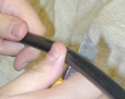
Here we have to take care not to cut too deep or we will damage the individual conductor insulation. A deep score is usually enough. Next you can bend the inner at the scored point to break it. You should see a small gap open through which you can see the individual insulated wires:

Once you have broken the insulation all round you can usually slide it off the wires. Using a twisting motion often helps a little.
(in practice it is probably better to leave a little more bedding on than shown in these photographs, so that it protrudes a little from the gland once fitted. This will offer a little more abrasion protection to the insulation on the conductors)
Step 4 - fitting the gland cone section
The cone section of the gland needs to slide between the inner insulation of the cable and under all the armour wires. To make this easy to do you need to splay the wires out a little first. One way to do this is the hold the cable in one hand, and the inner section of the cable in the other, and pull it to one side bending some of the amour wires out where they leave the outer sheath. Now move the inner round in an "orbiting" motion, so as to splay out all the wires:

Once the wires are splayed out, you can slide the cone section onto the end of the wire. Take care to ensure that none of the armour wires slip inside the cone, or they will damage the inner bedding insulation when you tighten up the gland nuts:

Next slide up the armour gripping ring:

And finally screw the armour locking back nut onto the cone section. This will force the grip ring up the cone section of the gland and trap the armour wires firmly in the gland. Use a pair of spanners to tighten the gland parts:

Step 5 - sealing the back of the gland
Now the armour is correctly clamped we can fit the cable sealing nut if we have one. This works like a compression fitting and sandwiches the internal rubber sealing sleeve against the outer insulation of the cable making it watertight:

Step 6 - Connecting to your box
Now the gland is fitted to the cable we can attach it to the actual box or panel that the cable is intended to connect to. For the smaller SWAs a 20mm knock out makes an ideal termination hole. Metal boxes often have pre-made holes ready to take SWA and conduit glands. Plastic ones will often need a knockout trimming out with a sharp knife first.
If you don't have an appropriate sized entry hole, (or you have the sort of hard plastic box that looks like it will shatter as soon as you look at it), then a small 20mm hole saw is ideal for making a suitable hole:

For this example we will terminate the gland on a standard metal box (this is a poor example in reality since you would be very unlikely to ever terminate at a flush mounting box like this since the gland assembly will need to remain accessible for maintenance (being a screwed electrical connection) - but it was what was to hand when the camera was poised! A more typical metal box would be one of the surface mounting metal clad types):

To make an effective earth connection to the armour there are a several ways of doing it. The standard way to do it is using the supplied earth tag (aka "banjo tag") and lock nut. If you need to keep the whole connection within the box then you may need to start by bending the tag a bit:

This will make fixing the earth wire to the tag simpler. Usually bolting your wire (via a suitable crimped terminal) is the easiest way to fix to the tag in the field. You can also solder to it but this is not always easy since there is a fair bit of metalwork to heat. If you do solder to the tag it is better to do it before it is mounted on the gland and in the box. On plastic boxes this will save you melting the plastic, and on metal ones it stops the extra metal conducting all the heat away and making it hard to solder.
The tag is now clamped between the box wall and the lock nut:

To bolt your wire to the tag it is best to crimp a ring terminal to the end of your wire:

In this circumstance it is often better to leave the tag flat, and drill a matching hole in the enclosure that lines up with the terminal hole on the tag. That way you can now bolt right through the tag and the enclosure. If you use a pan headed bolt, with the head on the outside of the box it does not look too untidy either. Note doing this is not recommended for boxes that need to remain completely waterproof.
A nicer solution however is to dispense with the tag and lock nut altogether, and use one of the proprietary fixing nuts like this that act as both lock nut, and also allow eye terminals to be screwed or bolted directly onto the nut.
With metal enclosures and boxes it is also acceptable to do away with the tag altogether and just rely on the interface between the gland and the box. If you are doing this it is vital that the mating surfaces of the box are cleaned to ensure no corrosion or paint will interfere with the connection, and also that the back nut is done up tightly. Note also that when the enclosure you are connecting to is to house an accessory (e.g. a socket) to comply with BS7671 [543-02-07], The earthing terminal of the enclosure must also be connected by a separate wire to the earth terminal on the accessory. Particular care is needed if the mounting plate that the gland fixes to is removable, since one may not rely on the screws that hold it as being a good enough earth connection on their own.
The final job is to slide the plastic boot into place, making a nice neat job:

Job Done! You can now get on and do the wiring... and the other end of the cable!
Finally, unless you do lots of work with SWA, don't be surprised if fitting a gland properly takes 15 mins or more.
See Also
- Wiki Contents
- Wiki Subject Categories
- Cables
- Taking electricity outside
- Wiring colour codes
- Cable Resistances