Wacom tablet upgrade - serial to USB
This is probably a bit of a niche project, but the other three of you out there with similar vintage hardware might find it useful!
Many years ago I bought a Wacom Digitizer II graphics tablet. Now aside from being way too big (it turns out when they say "A4 tablet", they actually mean its the long dimension of A4 in both directions! So add on a bezel and it's probably about 15" square), it actually worked very well, and was a much more natural way to touch up photos, or select complicated items to extract from the background in Photoshop.
Now the same tablet has lasted through many PC upgrades. However as time progressed it got progressively more difficult to get working with later OS versions, and especially with the switch to 64 bit versions of windows. Also this was a RS232 serial tablet, and Wacom dropped driver support for serial tablets some time back. While It was possible for a while to get it working with serial to USB adaptors, that eventually became impossible as well as the serial tablet drivers don't appear to be available in 64 bit versions.
So before deciding to chuck it out, I thought it worth seeing if there was a way to convert it to USB operation... this is that story!
Investigation
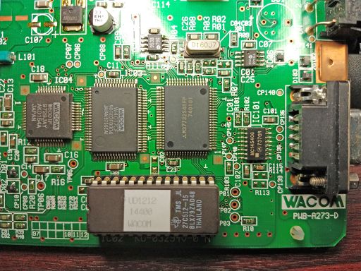
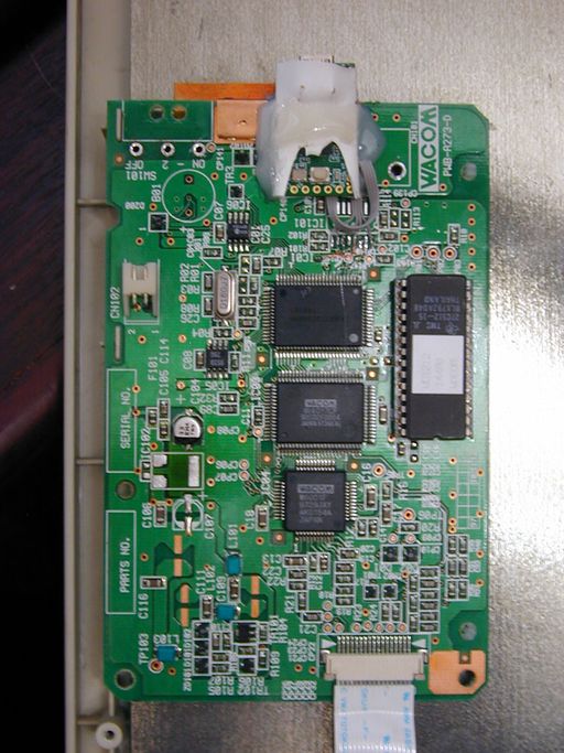
A quick disassembly got at the existing PCB. A mostly surface mount multilayer board about 4 x 3" in size. Fortunately relatively large scale surface mount by today's standards, so not to difficult to rework by hand without too much specialist gear:
The main components being a couple of Wacom custom chips, and a surprisingly powerful 16MHz Mitsubishi micro-controller and a rather incongruous looking 27C512 UV EPROM in a socket (decent turned pin quality socket as well!).
The plan being to work out how the RS232 interface was implemented, and see if that could be altered to allow a small embedded micro-controller like an Arduino or similar to be connected up in its place. This would then in turn provide the USB interface to the computer. The last bit of the puzzle would be to make the micro controller do a sufficiently good emulation of a USB tablet's firmware to convince the windows driver that it was talking to a proper USB tablet.
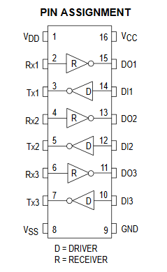
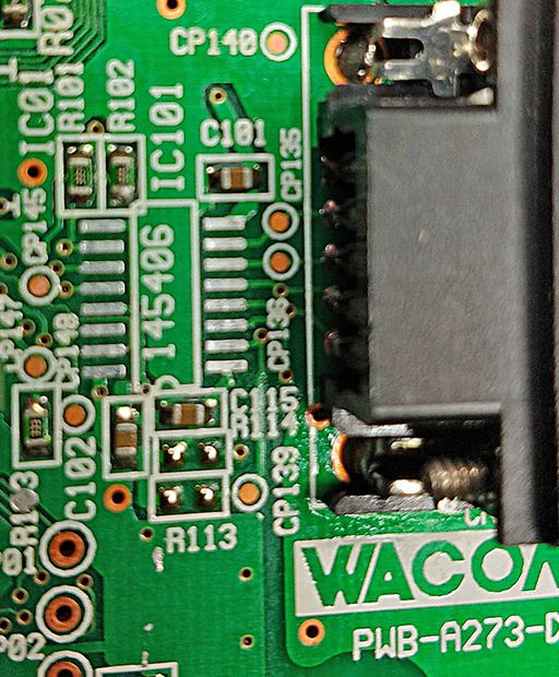
So the first thing I wanted to find out was how the RS232 interface was being generated. Research suggested that many tablets of this vintage used MAX232 or MAX202 charge pump level shifting ICs. It turns out that this one was using a Motorola MC145406 Driver/Receiver chip instead.It does the same job but is not quite as nifty as the old Maxim devices since it needs a double rail power supply to generate the -ve voltages on the RS232 side whereas the MAX232 can do it all from a single rail 5V supply.
I used a multimeter to "buzz out" connections between all the pins on the serial socket on the tablet, and the pins on the chip. Then referring to the chip's data sheet work out which TTL level pins were used for which function.
This got as far as:
Remember that the connector on the tablet is in the Data Communications Equipment (DCE) configuration (i.e. the end that would typically be on a device like a dial up modem) but the signal names are those used by the Data Terminal Equipment (DTE) (typically the computer). So there is a bit of mental agility required to remember that the receive pin on the DCE's connector is actually an output and not an input, since it will ultimately feed the receive pin on the DTE. (Modem cables are usually pin for pin "straight through" wiring).
So it looked like the only ones of particular interest would be the Ground, Tx and Rx lines to the outside world. and possibly the DTR and RTS handshaking lines since these are inputs and I don't know if the code on the tablet actually uses them.
Starting Work
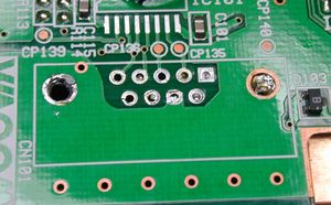
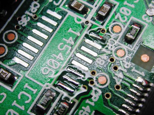
Next job was to remove the driver chip:
I did this with some Chip Quick low melting point bismuth alloy solder (you simply apply flux and a liberal amount of the alloy it to the joints of the SMD device with a normal soldering iron. It mixes with the solder on the board and allows it to stay molten for long enough that you can get all the pins melted at once with just a normal soldering iron). The SM device then lifts off cleanly without stressing the pads. A quick cleanup with a soldering iron, and then some de-solder braid to finish the job.
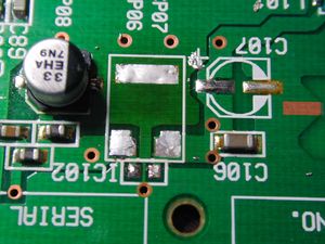
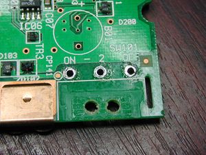
While I was removing things, I also took off the DB9 connector and the power switch since these would not be used. (the plan being to power the whole tablet and its new interface board via USB) thus getting rid of the need for the external PSU. This meant that I could also get shot of the 7805 5V regulator that was used to derive the boards 5V supply from the incoming 9V that was stuffed up pin 8 of the RS232 lead. (the tablet had an unusual DB9 connector that plugged into the computer with a 2.1mm power socket moulded into the back of it. An external PSU connected to this to feed 9V to the tablet).
Removing the regulator was not strictly necessary, but since I was ultimately going to be back feeding its output pin with 5V from the USB power rail, I thought I might as well while I was at it. (I needed to use my hot air soldering station to get enough heat into this to make its solder reflow since it was sat on a large area of ground plane)
Choosing a micro-controller
A bit of luck revealed that some folks had been here before, and had already reverse engineered the Wacom tablet protocols, and implemented the necessary translations to convince a windows PC that it had a tablet plugged into it. This had been done using a Teensy 2 micro-controller This is an 8 bit Atmel ATMega AVR based development board. It has plenty of I/O for this application, and a USB port. More importantly the USB port on the ATmega32u4 micro-controller used by Teensy, is a full implementation of USB that can be made to look like any kind of USB device - unlike that on many Arduino style boards than can only function as a USB serial port. For this application we need to pretend to be a windows compatible Human Interface Device (HID) as a minimum, and preferably as a convincing Wacom tablet to keep the windows tablet driver software happy.
Wiring Up
Now to the wiring up. The only connections we need between Teensy and the Wacom board are 5V, GND, Tx, and Rx. Then for completeness we also want to tie the DTR and RTS lines low to fix them in the "inactive" state. So the wiring required from Teensy to PCB is:
| Teensy signal pin | MC14506 pin position | Other Connections | Teensy 2 pinout |
|---|---|---|---|
| GND | 9 | 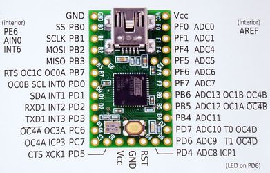
| |
| Vcc / 5V | 16 | ||
| Rx / D2 | 10 | ||
| Tx / D3 | 11 | ||
| 13 | GND | ||
| 15 | GND |
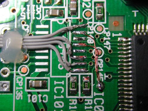
The pin spacing on the board is fairly small, so I snipped a bit of ribbon cable out of an old 80 way IDE interface cable (this is the finer pitch ribbon with the extra screening ground lines between each signal).
I terminated this on the Teensy in the through holes provided for the purpose. Then tinned up the pads that used to connect to the line driver IC:
Then I could tin the wire ends and place each onto the pads:
To tie the handshake pins to a convenient ground point I dug out my old "Verowire" pen (purchased some 40 years ago when it seemed like a snazzy gadget, but it turned out it rarely got used at the time. It turns out its got a new lease of life as a "mod wire" pen on SMD boards, since the insulated wire is fine enough to get onto close pitch pads, and its insulated with a polymer coating that boils off when you solder to it - so there is no need to strip or prepare the wire prior to use. Just solder one end, drag out wire to the other, solder that, and then a few wiggles of the pen tip will fracture the wire flush with the solder joint).
I fixed the ribbon in place with a blob of hot melt glue.
Testing
At this point we could do some basic tests. First I buzzed out all the wiring to make sure there were no shorts, and that all the connections that should be there were. Then I checked that Teensy powers up and is recognised on the USB, and that it is also able to power up the tablet. The tablet LED activity light was responding to pen touches as it should, Lastly I had a poke around with a logic probe to check that I could see serial data flowing into teensy when I moved the pen on the tablet.
So far so good. However at this stage all we have is a new PSU for the tablet, and some default software in Teensy, dutifully flashing its LED to say "Its Alive Master!"
Now we need software.
Software for Teensy
This bit was easy, someone else had done all the hard work! Nip over to GitHub and grab a copy of "Waxbee"Not only does this include all the driver code required, it also comes with multiple configuration files for a number of old Wacom tablets including the serial models and the old Apple Desktop Bus versions. This is all packaged up with a nice Java front end GUI to allow selection of the required version and handle programming teensy.
I experimented with a few different versions, but settled on the version for the UD 1212-R tablet, that emulated an Intuos2 USB tablet.
One this is programmed (takes about 5 seconds!), the PC will then recognise the USB device, and probably also identify it as a Human Interface Device (HID), with a USB virtual serial port. You might even be able to use the tablet as a basic mouse pointer at this stage depending on what version of windows you have and what mood its in!
Software for Windows
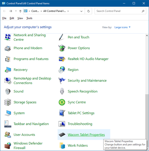
Last stage is to find some Wacom software for the PC that will recognise the HID as a tablet, and enable all the extra capabilities like pressure sensitivity, and pen angle detection. I wanted it to run under Win 10 Pro x64, but found it was actually better to get the driver version designated for XP, Vista, and Win 7 (the more recent versions did not seem keen to recognize "Frankentablet"). So I downloaded wacomtablet_6.2.0w5.exe from here. That was quite content to install the necessary control panel app:
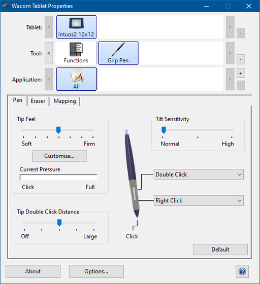
and convince it that it was talking to an Intuos2:
Application Test
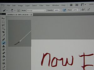
The final test was to try it in photoshop - and yay, I can now write as badly on a computer as I can on paper!
Tarting up
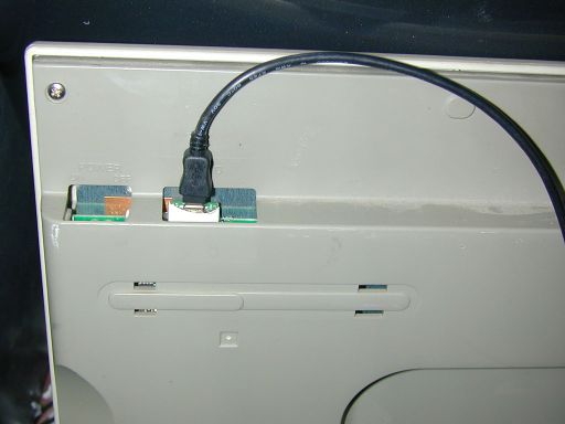
The final job was to heatshrink Teensy, and hot snot her into place on the PCB so that the USB pokes out the back of the tablet:
Then put the back cover on:
See Also
After having done some of the investigation work the hard way, I managed to find some old web forum posts that also covered this mod. However the forum seems to have vanished, but some of it is available from the wayback machine here.
