Earthing Types
Earthing Types
Mains electricity systems are categorised in the UK according to how the earthing is implemented. The common ones are TN-S, TN-C-S and TT. You will sometimes see these referred to in questions and answers about mains wiring.
Note that in these descriptions, 'system' includes both the supply and the installation, and 'live parts' includes the neutral conductor.
BS 7671 lists five types of earthing system:
- TN-S
- TN-C-S
- TT
- TN-C
- IT
Where those letters indicate:
- T = Earth (from the French word Terre)
- N = Neutral
- S = Separate
- C = Combined
- I = Isolated
First letter:
T The live parts in the system have one or more direct connections to earth.
I The live parts in the system have no connection to earth, or are connected only through a high impedance.
Second letter:
T All exposed conductive parts are connected via your earth conductors to a local ground connection.
N All exposed conductive parts are connected via your earth conductors to the earth provided by the supplier.
Remaining letter(s):
C Combined neutral and protective earth functions (same conductor).
S Separate neutral and protective earth functions (separate conductors).
Valid system types in the 17th Edition IEE regulations:
TN-C No separate earth conductors anywhere - neutral used as earth throughout supply and installation (very rarely used).
TN-S Probably most common in older housing stock, with supplier providing a separate earth conductor back to the substation.
TN-C-S (Protective Multiple Earthing) Supply combines neutral and earth, but they are separated out in the installation. More common in newer houses.
TT No earth provided by supplier; installation requires its own earth rod etc. Note that a TT earth will frequently not offer a low enough impedance by itself to provide adequate circuit protection. Hence TT systems must use a RCD for additional protection. You can find details on installing a TT earth here.
- 1950s-1970s TT installs used an ELCB instead of an RCD
- 1950s and older TT installs had no ELCB or RCD, and are non-EEBAD. Such setups are unsafe, a single fault path to earth anywhere on the system can leave the whole house earthing system live long term.
IT Supply is e.g. portable generator with no earth connection, installation supplies own earth rod.
- Some domestic IT installs exist that were originally TT with water pipe earth, but the waterpipe got replaced later with plastic. Some such systems may have usable (but not ideal) earthing via some other metal feature, sometimes not. Any such systems should have their earthing fixed!
- In the case of a generator feeding tools or temporary wiring there is more often no reliable earth connection
A useful IEE document on earthing
Main Earthing Terminal
The main earthing terminal (MET) in a building is the place where the main earth, the main equipotential bonding conductors, and the connection to the circuit protective conductors for installation's circuits meet. On smaller installations this will frequently be hidden away inside a consumer unit, where the main earth bus bar typically has additional connection points for the connection to the main earth, and also the bonding conductors.
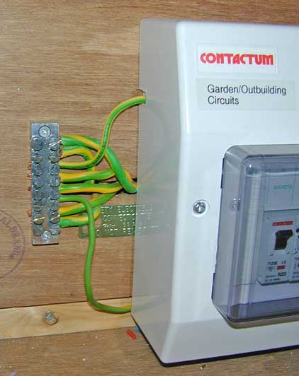
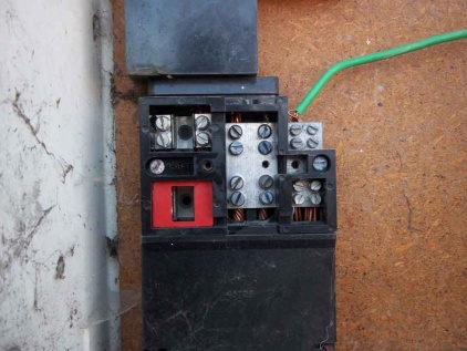
On larger installations (often ones that employ more than one CU), the MET may be an external terminal block similar to that shown here:
or the MET may be a similar connection block contained in some form of insulated box or fitting.
Identify your Earthing type
By careful inspection of the wiring arrangements of your electricity supply, it is usually possible to identify the earthing system in use in your property. It should also be possible to query your electricity supplier, who should have records of the system being used for each customer.
TN-S
With TN-S earthing the main earth is carried to the installation via a separate conductor from the substation. This is usually the metal sheath of the supply cable, although could in theory also be a dedicated wire. TN-S installations can usually be recognised by an earth connection being made directly to the incoming cable sheath - typically before it enters the cable head end.
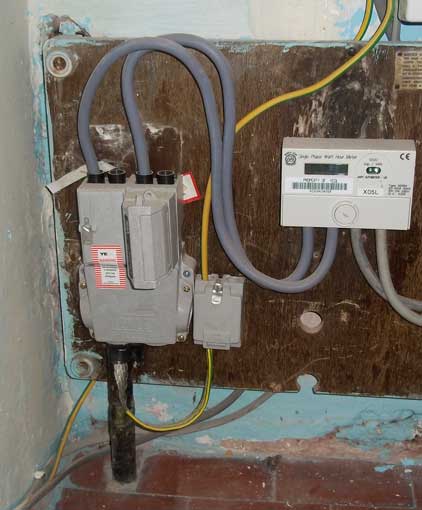
In this example the cable enters the property underground and emerges in to a typical main cutout unit incorporating the main fuse. The cable in this case obviously has a braided metal screen in its construction which is connected to the supply earth. The smaller grey box to the right of the cable head end is a junction box serving as the Main Earth Terminal, and it connects the cable braid to the more usual 16mm² earth single that goes on to feed the consumer unit. (the other protective wire you can see in the bottom left of the frame is the main equipotential bond from the incoming gas main, which has been terminated directly in the consumer unit rather than the main earth terminal junction box.
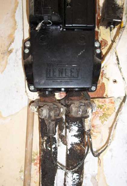
The next photograph shows a pair of rather scabby underground cables entering the property. One is the mains feed in, and the second is a feed out to the adjacent property. Here you can see a (somewhat undersized and grotty looking) earth single connected to the clamps on the armour at the top of the underground cables. This is in turn connected to the main earth terminal.
This example is a good illustration of how it may not always be obvious what type of system is in use. An initial look shows what could be a TN-C-S cutout (and if you look in the following section you will see that this particular model of cutout is frequently used in that way) since there is no obvious connection to an incoming cable sheath.
However with one section of the cover removed, it becomes clear that the optional link between Neutral and Earth connection blocks is not present:
Removing the lower section tells the full story. The incoming cable (and the secondary feed that is taken to the neighbouring property) is a split concentric cable with discrete earth and neutral conductors in the outer layer of wires.
WARNING Live and unfused terminals are exposed during this procedure - only to be attempted by skilled operatives with live working training
TN-C-S
TN-C-S (aka PME or Protective Multiple Earthing), installations can be recognised by the earth conductor being connected to the cable head end such that it can be connected to the main incoming combined Neutral and Earth conductor (known as a PEN or Protective Earth & Neutral conductor)
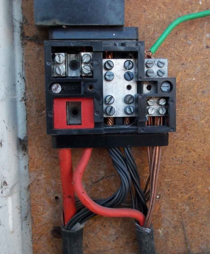
In this example the supply enters via a cable at the base of the cutout. Note that a service connector block has been used as a main earth terminal, and the connection to the cable head end can be clearly seen (note that the wire making this connection is actually undersized in this photograph - it should be at least 16mm² and not the 6mm² used here, and dates back to the 1970's when such installs were common - see side photos for the rectification)

WARNING Live and unfused terminals are exposed during this procedure - only to be attempted by skilled operatives with live working training
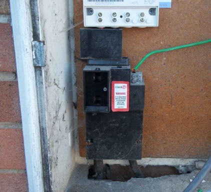
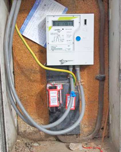
The next example shows inside an external meter box set into a cavity wall. An overhead supply cable can be seen entering the box at the top right hand side, and dropping to the head end. The tails and main earth wire then head off into the building to connect to the consumer unit.
TT Earthing
TT Systems are normally recognised by the lack of any earth connection to the incoming supply cable sheath or to the incoming neutral (i.e. combined earth and neutral) conductor.
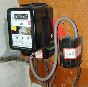
An older example:
Here the incoming supply is by way of overhead cables. These terminate on the outside of the building and separate wires with fibre reinforced rubber insulation bring the supply into the building. The neutral connection is made directly to the meter, and the live connection is via a straightforward main cutout fuse and then to the meter.
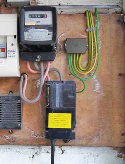
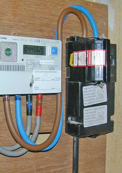
A slightly more up to date TT installation:
Here the supply is again via overhead wires, but this time is converted to a concentric supply cable from the connection point outside the building to the main cutout. The cutout in this case is a more sophisticated device through which both neutral and live conductors pass. It has provision for the connection of an earth conductor the the incoming neutral when used on TN-C-S (PME) installations (note the same brand is used in one of the PME setups shown above), however in this case you can see that the only connections actually used are the live an neutral feeds to the (electronic) meter, even though the supply itself has been upgraded to support PME, as evidenced by the (slightly obscured) yellow PME sticker on the side of the cutout).
Other Earthing Types
TN-S, TN-C-S, and TT represent the vast majority of earthing systems you will see in common use. TN-C is exceedingly rare, and unlikely to be seen in the wild.
IT will usually only be seen on installations using private generators (either for primary or backup power). When a generator is feeding an entire property, for most practical purposes it will appear much like TT installations. (note that is it common practice when using a generator, to tie one of its outputs to ground via an earth rod anyway, rather than leave both sides floating - this in effect makes the system TT)
When using a generator in isolation, say to feed power tools being used on a building site, then it is common to leave all parts of the system unearthed and use the 110V output to power suitable tools. In this way both "live" and "neutral" connections on the generator are floating at an arbitrary potential with respect to earth, and making accidental connection to either of them does not complete a circuit via earth that would allow a dangerous shock current to flow. A similar situation exists when using a 110V yellow site transformer.
Finally note that other arrangements may be seen that appear to be a hybrid of the systems described here. Many of these will be a systems that have been converted at some point, e.g. an old TT system might have been converted TN-C-S, but the old earth rod was not disconnected.
Earth impedances
The guideline figures that one uses in the absence of actual values, are 0.35 ohms for TN-C-S and 0.8 ohms for TN-S. In reality either can be significantly lower.
TT earth impedances vary a lot, from a few ohms up to hundreds.
IT uses no (intentional) earth connection
