Electrical Installation
This article is all about the non engineering side of electrical installations. Its purpose is to explain some of the techniques that are used when installing electrical equipment and wiring in typical domestic situations.
Cabling
Cables can be run in a large number of places and ways. However, some places are better than others, and certain rules need to be followed to comply with the wiring regulations. In addition to the practical issues of cable routing, one also needs to think about what materials you are placing the cable in/under etc. since these may have effects that you need to take into account in the electrical design. E.g. a cable buried in an insulating material will not be able to lose heat as quickly as normal, and this means that the maximum current it is allowed to carry is reduced.
General routing issues
Care needs to be taken when selecting cable routes to minimise the risk of damage to the cable at a later date, and also reduce the possibility of it causing or suffering interference issues. In particular:
- Avoid routes that require the cable to pass over sharp edges or objects
- Avoid hot areas around heating appliances etc.
- Keep mains wires a minimum of 50mm away from data, telecomms, and AV wiring wherever possible. Crossing a wire at a right angle will result in less potential for interference that running adjacent to it. If you need to route mains and other cables in trunking then use segregated trunking designed for the purpose.
- Follow the wiring regs expected zones for cables - i.e. directly in line with visible accessories - horizontally or vertically, plus in a 150mm band in room corners or at wall to ceiling junctions.
Wall chasing
Burying a cable in a wall is a traditional way to hide and protect the cable. Modern cables can be buried directly in plaster, or protected with capping before plastering. Before a cable can be buried however, a chase needs to be cut!
See the wall chaser article for more detail on the options for cutting cable chases in plaster and masonry.
Also don't forget the lazy option of using a pull switch rather than a wall mounted one, or a wireless room thermostat/door bell/network connection/etc in place of a wired one.
Getting past coving and skirtings
It is all well and good chasing a wall with your trusty SDS drill or wall chaser, but what happens when you reach some architectural feature that you don't want to go hacking through, like a deep skirting board or ornate plaster cornice or moulding?
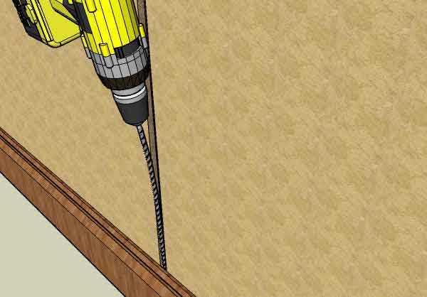
- Long drill bit: A very long drill bit (we are talking a minimum of 400mm here to get behind small items like picture or dado rails, or more realistically a stonking great 1m long bit for skirtings and coving!) can be a handy way to continue a chase behind the feature you are trying to avoid. Ideally one would need to drill straight up or down through the plaster to achieve this. This is usually impossible since you can't get the drill in the right place, or at the right angle since the wall is in the way. With small obstructions (dado etc) this may not matter, drilling down behind it at a slight angle will still be ok. For a longer vertical chase, the longer bit will be required. The trick here is to apply some sideways force to the bit as you drill. It should be possible to bend the drill such that its tip is parallel to the wall, while keeping the drill body and your hands at the slight angle required due to the obstruction of the wall. Its worth putting your foot against the skirting to support it, just to make sure it does not get pulled away from the wall (where the drilling dust could fall behind it, and keep it bulged out when you are finished if you are unlucky).
- Cranked gouging chisel: specially made SDS gouges can also work well for getting behind smaller items.
- Using the other side of the wall: As simple as it sounds, in some cases the solution to avoiding difficult chases, might be to simply use the other side of the wall. This can be ideal for a cable chase on a tiled wall in a bathroom. It can also often save time where adjacent rooms have light switches "back to back" on the dividing wall - only one chase is required for the pair. Note: one will need to take care that cable routes are within the prescribed zones expected - even if this means installing an extra accessory to mark the position.
- A long threaded bar and a lump hammer. A long SDS bit may still damage very deep coving as it is not always possible to get the drill into a vertical position. A slightly bent threaded bar can be knocked up behind deep coving and not damage it.
Under floors
Cables are also often taken under suspended floors or even sometimes placed into chases cut into concrete ones.
Lifting floors
| Type of floor | Methods |
|---|---|
| Traditional floorboards | A traditional boarded floor is one of the easier ones to get under! The traditional approach simply uses a pry bar and or bolster chisels to lever it up. Sometimes you also need to cut a board. There are a number of approaches to this:
In each case, pulling the more obvious nails and removing screws first can help greatly. One technique that can be used for freeing particularly hard to remove nails is to simply drill round it with a small (c. 14mm) holesaw. This cuts a plug of wood from the board with the nail still in it. Once the board is lifted, then nail and its remaining wood collar can be removed and the board patched with a wood plug of suitable size. |
| Tongue and groove floor boards | Similar to the above, except you will also have to rip cut through (or split off) the tongue on the board first, in order to be able to lift it. |
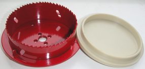
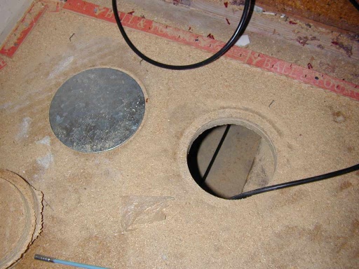
| Chipboard sheet | Generally far harder to work with since the boards are not only tongue and grooved at the edges, they are also large (typically 8' x 2'). In many modern houses, it's also not uncommon for the partition walls to be built over the floor panels, or at least the skirtings etc to be fixed over them. This can make removal of a whole board impossible. The best way to deal with this floor is to cut an access panel:
The result looks like: (shown with galvanised steel cap plate on left hole) |
| Laminate | While not easy, it is possible to remove a plank of laminate in a floor. For the click-together type, it may be simplest to start un-clicking panels at the edge of the room, and work your way back to where you need your access point. For glued panels, you will need to cut out a board. The way to do this is with a circular saw (preferably a small one - cordless ones are ideal). Set the cut depth to laminate thickness, and cut through the board all round, close to its perimeter. Once the main bit is removed, use a chisel to break away the remaining edges from the adjacent boards.
To replace the board you will need to cut away the underside section of the groove edges of the new plank, and then glue and lower the new board into place. Depending on how cleanly you were able to remove the tongue from the groove of the adjacent board, you may also need to cut this off the new board. |
| Concrete | Concrete floor screeds can be chased, but care should be taken. Many 'suspended' or 'block and beam' concrete floors are made from interlocking prefabricated components and are fully structural, and should not be chased without consulting the manufacturers or a structural engineer. When installing conduit in floors, consideration should be given to the possibility of condensation in the conduit draining to the lowest levels. |
Entry via a ceiling
The lateral thinkers way to get under a "difficult" upstairs floor is via the ceiling of the room below. In many cases some new plasterboard and a bit of patching is a much quicker solution that lifting an engineered wood floor and underlay, or clearing a particularly cluttered room.
Joists
Most floors are held up by these. When they are running the direction you want your wire to go, all is well with the world and you have a nice easy job (mostly!) However, when you want to get across them, then life is more difficult! Many of the techniques listed elsewhere in this article for dealing with hollow walls can be applied to joists as well. However, given they are holding your floors and ceilings up, you want to be a little careful how you go hacking them about.
| Technique | Notes |
|---|---|
| Drilling | You can drill through the side of a joist. However, you should only drill in the middle of the side, and not at the top or bottom, since the middle section has least stress on it. You should also not drill near to the ends of a joist, since this increases the possibility that the end of the joist could fail in "shear" (i.e. split along the length at the end, making the whole lot weaker). Another advantage of drilling the centre of the joist, is that your cables should be well away from any nails or screws.
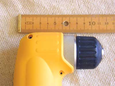
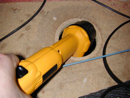
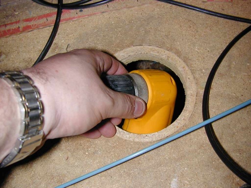
To meet current building regulations, the hole does not want to be more than 0.25 times the total joist height - so a 2" hole on a 8" joist is about the limit. It should also not go closer to the end of the joist than 1/4 of the span (so no nearer than 1m from the end of a 4m joist), and no closer to the centre than 0.4 times the span. Take care not to over stuff the holes, since you don't want to reduce the current carrying capacity of your cables by bunching lots of circuits together. If you need another hole, leave a gap equal to at least three diameters between one and the next. The posh way to get between joists is with an angle drill: Fitted with a short auger or a spade bit with part of the shaft cut down, these will get between most joists. However, you may find a small cordless drill or an impact driver will also fit. If you can't get a drill in, then a long drill bit (or a drill bit fitted on an extension bar) at an angle can be a last resort. Combined with a board access hole saw like that shown above, you can normally get an angle drill into the floor void. Start by removing the drill bit, and offering the battery end through: Then follow with the rest of the tool. Refit the drill bit once in the floor void: |
| Notching | Notching is the process of hacking a lump out of the top of the joist (tenon saw and chisel, or oscillating saw being the easiest options here). Unlike drilling, this is better done at the ends of the joist and not near the middle of the span, since it weakens it in bending but not as much in shear.
A notch should be no deeper than 1/8th of the joist depth (so 1" on a 8" deep joist is the limit). Notches must go between 0.07 and 0.25 times the span. So with a 4m joist that would be anywhere between 280mm and 1m from either end. Additional care must be taken to protect the cables from nails and screws. You can buy metal plates to place over the top of notches to achieve this. |
Over ceilings
In some cases, the same as under a floor! However, this also includes over false ceilings (which, if you have lots of wires to hide or lots of ceiling piercing lights to install, may be well worth building for the purpose). It also includes through loft spaces. One caution to watch is to keep modern PVC cable away from polystyrene insulation (the plasticiser leaches out of the PVC into the polystyrene, leaving a gooey mess, and rather brittle cable insulation).
In hollow walls
It is also sometimes possible to drop a wire down a hollow stud wall (either plasterboard or lath and plaster). Note: it is not recommended to place wires in the cavity of exterior walls, where they could cause dampness bridging, and be adversely affected by cavity wall insulation injected at a later stage.
Getting wires into a stud wall in the first place is easy to do when building it. However, at a later date it is not as easy and you may meet a few obstacles:
| Problem | Solutions |
|---|---|
| Catching a wire | Feeding a wire along the inside of a wall is one thing, but getting the free end out again without making a hand sized hole in the wall is another problem! Techniques to try include:
|
| Getting past studs and noggins | It is rather hard to drill a hole through the side of a lump of wood if all you can see is a board covering its front face! However, there are ways:
|
| Getting access into the wall | With plasterboard stud walls, easy access hatches can be cut with a drywall saw, a holesaw, or a sharp knife. One easy to repair technique for such holes is to simply site a new double socket where you need your hatch - that way you use the socket and a dry lining box to fill the hole.
If you need to make an invisible repair to a plasterboard wall, then start by cutting some battens just a bit longer than the span of the hole. Insert these through the hole, and glue or screw them into position against the back of the plasterboard. Now refit the removed section of plasterboard and screw this to the battens. Use some board filling compound to patch the gaps and screw heads. Finally a quick sand will leave a surface as good as new. |
Pulling Cables
Pull wires / cords / tapes
Ideal for getting wires through tortuous paths. There are specialist tapes and cords for the purpose, but almost any bit of string or even and old cable may be used. Fishing line is often very good in that it is strong, long, thin, slippery, and cheap! The real art with any pull string is how you get it into location in the first place! Some of the more imaginative options include:
- Add a weight or ball to the end and drop, throw, catapult, or otherwise propel it in the desired direction. A metal weight like a small bit of chain or threaded nut can make retrieving the end easy with a magnet on a stick, even through the surface of walls & ceilings.
- Radio controlled cars and other self propelled toys, can be driven or even flown to the destination while towing a wire - handy for ground floor voids that are not big enough (or too full of rat crap) to make climbing under yourself desirable.
- Small children can often be pressed into service with some bribery ;-)
- Cat, cable tie, and a sardine might also work!
There is a whole subset of these, for getting a pull cord through ducts and pipes. Most involve either a vacuum cleaner to suck something through the ducts, or a compressor to blow something through it. Rags, plastic bags, and tennis balls being tried and tested candidates.
Also when pulling pull cords, you may need to allow for the possibility that all you will pull with the first cord is a stronger cord! Working your way up to the particularly heavy or stiff cable that ultimately needs to get through.
One handy tip when laying in wires in many cases, is to pull a new cord through with each wire. That way you can always add more later. A refinement on this technique for pulling lots of cables is to use a double length pull cord with the cable being pulled fixed to a knotted loop in the middle of the cord. That way you can pull through the new cable, disconnect, and then pull the string back using the extended length that is still in the cable route.
Using existing cables
Often there is an existing cable in place that follows the desired route, sometimes this can be temporarily disconnected and used to pull another cable (plus a string or similar, since you will want to pull the original cable back into place after!)
They key to success with any cable pulling technique is making sure that the join between draw wire and new wire is secure, and won't snag during the pull. Crude knots are bulky and likely to catch. Side by side, joins secured by insulating tape are easy, but suffer with a double thickness section and a lip that can catch. Often the best technique relies on stripping down the wire a little, joining the inner conductors, and then taping over the joint to make a join that is inline, and no wider than the original cable.
A technique suggested by an expert aerial rigger is: "...usually use another piece of coax. The thing is to make sure that the joint is a smaller diameter than the cables, and that it has no edges or protuberances that might snag.
So: Carefully strip back about three inches of outer sheath. Preserve the braid by either unravelling it or pushing it back over the sheath. Cut the dielectric off without nicking the inner. Pull the braid back over the inner. Do this for both cables, the puller and the pulled. Tie a reef knot in the two lengths of braid/inner, but make sure the knot is fairly close to the remaining plastic on both cables, otherwise the joint is too flexible near the knot and can snag on a corner. Wrap the joint with pvc tape, overlapping the plastic just once, pulling the tape tight, adding rigidity but being careful not to exceed the cable diameter. Make sure the tape bridges any protuberances.
Make sure someone feeds the cable as you pull, because otherwise it's more likely to snag.
If it snags pull it back a yard then twist the pulling end one turn and try again. "
Lubricants
Sometimes some extra assistance is needed when getting wires and cables through tight spaces and into pipes, ducts, conduits etc. There are specialist cable pulling lubricants available like "Yellow 77" that are designed for this purpose and won't hurt or react with the cable in any way. However, other substances are often used:
- Talc
- Grease (silicone is better - it won't attack the plastic)
- PTFE sprays
- WD40 (not much good - but is sometimes better than nothing)
- Soap / washing up liquid
(don't use graphite power - it conducts electricity!)
Push rods and sticks
Very useful for getting wires through awkward spaces. The simplest (and a widely used) stand-in for "real" ones, are simply lengths of plastic conduit or trunking (and especially the lid off a bit of mini trunking!). The posher versions look rather like a narrow gauge version of a set of drain rods (which are themselves useful for heavier cables). Often made from fibreglass, they can be screwed together to make a very long stick (10m is not uncommon). The end of the stick can be equipped with hooks, loops, magnets and other gizmos to make getting them round corners, or catching cables or other rods easier.
One word or warning with the fibreglass sticks: wear gloves when handling them - otherwise you can get a nasty glass splinter!
Tools
The following is a big list of tools (in addition to all those mentioned specifically elsewhere!), some are essential, and some just handy to have. Essential in this case means these are tools that you need to do the job safely - you may be able to do it with less, but you may be putting yourself at risk when doing so.
Many of the mechanical aspects of wiring have little to do with the things that one traditionally associates with the work of an electrician, and are really nothing more than general building and carpentry tasks.
| Type | Description | Need |
|---|---|---|
| SDS Drill (3 function) & bits | The ability to not only drill holes, but also quickly and neatly chisel out holes for socket boxes, and neat wall chases make the SDS drill a wonderful time saver. | Very Handy |
| Cordless drill/driver & bits | In general cordless tools are very handy to have for electrical work since you will often be working in areas without power. Making holes, and fixing things in place probably come right near the top of the list of tasks faced by anyone undertaking electrical work. A medium size (say 14.4V or better) combi-drill is ideal for this sort of work. Having the hammer facility can make drilling holes into masonry for wall plugs far easier. | Very Handy |
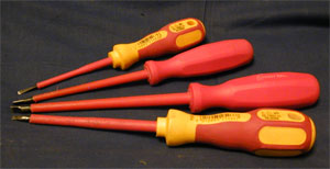
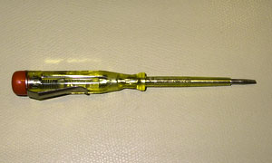
| Insulated screwdrivers (VDE) | VDE tools[1] are insulated and tested to to a high standard. This ensures that should the metal part of the tool make contact with live metalwork, no harm will come to the person holding the other end. These are cheap to buy, and essential for working safely on electrical installations. Not just for the rare occasions where live working is required, but for the far more typical cases where one is working in close proximity to live circuits, or even on circuits that really ought to be dead, but are not!
All things said and done, you can make do with some ordinary screwdrivers for jobs not involving work on electrical fittings etc, and you may choose to buy a limited set of VDE insulated drivers: a medium phillips (typical for MCB terminals) and a small and medium flat blade for other terminals. |
Essential |
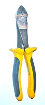
| Side Cutters
High leverage version - for heavy cables |
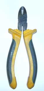
VDE insulated side cutters are essential (one day, you will pick the wrong cable to cut). Side cutters are used for cutting cables and wire to length, and they are also often invaluable for stripping cables of their outer insulation. Some cutters also include specific facilities for wire stripping, [eg]. | Essential |
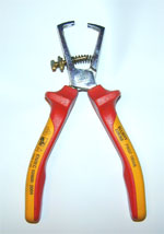
| Wire Strippers
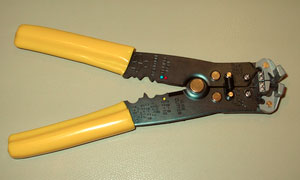
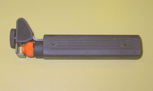
Automatic version For stripping outer sheath of twin & earth |
Good wire strippers make life very much simpler (while it is true that someone proficient with side cutters can often strip a wire quite satisfactorily with them as well, there is far more scope for bruised knuckles, damaged conductors, and tatty looking wire ends without them). The style of wire cutter is much a matter of personal preference. Side strippers are quick and easy to use - especially on smaller wires. The end action ones may be better for tough insulation found on the thicker and also special purpose wires. Some people also like to have an automatic wire stripper. These can make repeated stripping operations very much quicker.
The sheath strippers are designed to make removing the outer insulation of Twin & Earth easy. While this is usually easy enough to do at the end of a wire by simply cutting lengthways up the end with side cutters, grabbing the earth conductor, and tearing it out through the side of the cable, the sheath strippers come into their own should you wish to strip outer insulation from the middle of a section of cable - so as to achieve an unbroken wire connection to a socket in a ring circuit. |
Highly desirable |
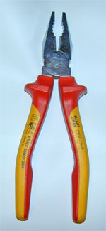
| Combination pliers | Regular square nosed medium set are useful for holding, bending, and twisting wires, tightening locknuts etc. In fact, anywhere you need extra gripping power. | Handy |
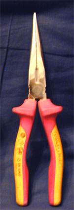
| Long nose pliers | A good pair of long nose pliers are the ideal tool for fishing wires out of awkward corners, and holding tricky wires in place as you tighten terminal screws. Note however, that even with VDE insulated ones, care must be taken, since they have a large expanse of exposed metalwork that could easily short against live parts or earthed casings. | Very Handy |
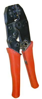
| Ratchet action cable crimper | Essential for making sound wire joints which will later become inaccessible, or where space is too restrictive to allow terminals (aka "choccie blocks") to be used. See the Cable crimping article for full details of how to use these. | Often Essential |
| 20mm Hole Saw | One of those universal truisms with many electrical accessories is that the "knock outs" are often in the wrong place, or failing that, won't actually knock out without wrecking something. A small hole saw is the ideal way to persuade them of the error of their ways! | Handy |
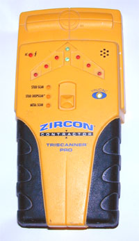
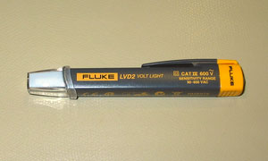
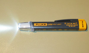
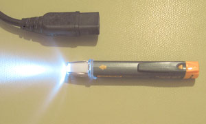
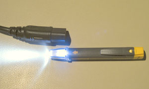
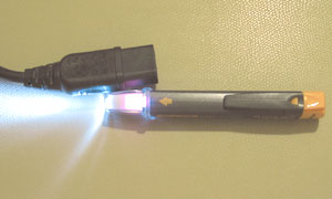
| Metal, voltage, and stud detector | One of these that actually works (like the one pictured) is a massive time saver. It can find studs behind plasterboard, and buried pipes and cables (and tell you when they are live). Note: the stud detection is defeated by foil-backed plasterboard, but you can still use the metal detection facility to find the nails or screws that are holding it to the studs! Failing this, a small strong magnet can prove very effective at finding screws, nails & brackets etc behind boards if you sweep them slowly across the board with your hand. Bear in mind, though, that non-ferromagnetic materials such as copper pipes & cables won't be detectable! | Well worth having |
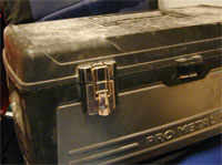
| Tool box you can sit on! | Not to be underestimated, but a decent tool box that is designed to be usable as a step is a wonderful time saving invention! Ideal for a quick seat to place you at socket height, they also help you reach ceiling fittings without needing a ladder in many cases (unless you are working in tall Victorian rooms, or were a bit short changed in the height department ;-)) | Very handy |
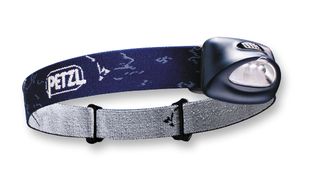
| Torch and/or Head Torch | Good reliable torches are often a must for many cable access jobs. LED units in particular are very good since they will run for a very long time on a set of batteries (keep spares in the toolbox though!). A Headtorch in particular can gain huge amounts of productivity when actually wiring since it puts the light exactly where you need it and leaves both hands free. | Very Handy |
| Knife | A sharp knife (like a plastic bodied snap off blade utility knife) is also often very useful. Jobs like stripping some types of cable are very much simpler with one. Just take care not to try cutting more solid items like plastic boxes with one - it will only end in tears! | Very Handy |
[1] Just in case you were wondering what VDE stands for, the answer is: It wouldn't help much as the words are German! It is an internationally accredited German testing and standards institute. In their own words:
- "The VDE Testing and Certification Institute is accredited on a national and international level for the area of testing and certification of electrotechnical equipment, components and systems. Testing of electrotechnical products is conducted for safety, electromagnetic compatibility and other characteristics."
Test gear
Advanced test gear
For anything other than basic alterations and additions to existing circuits, some more sophisticated test equipment is really required. These items can be bought as separate units or as an integrated multi-tester that combines all the functions. Again, you will probably live if you don't use this kit, but it is the only way you are actually going to prove that your wiring is performing as it should.
| Type | Description |
|---|---|
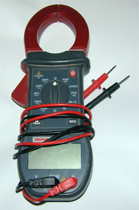
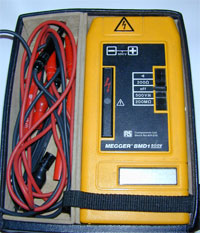
| Insulation resistance tester ("megger") | These are often multi function devices that measure wire resistances with good accuracy, and are also able to perform resistance measurements using a very high test voltage (e.g. 500V or more). This will detect any part of a circuit (or whole installation) that has failing or damaged insulation. These can be very handy for finding tricky faults causing nuisance tripping of RCDs for example.
Great care must be taken with these devices. Firstly, they will give you a shock if you hold the probes and push the test button. Secondly, you need to make sure there is nothing connected to the circuit under test that might be damaged by the high test voltage (some RCDs, dimmers, and electronic power supplies etc). |
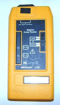
| Earth loop impedance tester | These are very useful devices that will allow you to measure the earth fault loop impedance at any socket in a circuit. This lets you prove the effectiveness of the earth, and establish data you will need for circuit design. They can also be used to measure the performance of earth rods. In many cases they will also let you measure the Prospective Short Circuit current and the Prospective Fault current of a circuit.
Older devices like the one pictured, perform tests using a fairly substantial test current. This is good in the sense that it proves that the earth really does work under simulated "fault" conditions, but has the downside of tripping any RCD protecting the circuit under test. More modern devices also have the capability of carrying out non-tripping tests. |
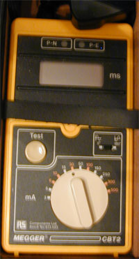
| RCD Tester | About the only way to properly test a RCD. These inject a user-selectable earth leakage current into a circuit, and then time how long (in 1/1000ths of seconds) it takes the RCD to disconnect the power. More sophisticated versions can also carry out "ramp" tests that slowly increase the leakage until the trip point is found.
Not only required for RCD tests, they can also often help establish the cause of nuisance trips. |
Good workmanship
Take care of your wires and they will last longer and give less potential problems in the future.
Mechanical protection
| Type | Description | ||||||||||||||||||||||||||||||||||||
|---|---|---|---|---|---|---|---|---|---|---|---|---|---|---|---|---|---|---|---|---|---|---|---|---|---|---|---|---|---|---|---|---|---|---|---|---|---|
| Capping | To protect cables from damage by plastering trowels, capping is ideal (plastic or metal). The advantage of capping over conduit is that it is easy to fit after a cable has been installed, and it won't substantially affect the cable's ability to lose heat. | ||||||||||||||||||||||||||||||||||||
| Plastic Conduit | Plastic conduit can be used for added protection to surface-run cables. Note: it is not well suited to burial since it offers little protection from drills, nails and screws, while lowering the current carrying capacity of the cable. | ||||||||||||||||||||||||||||||||||||
| Metal conduit | Metal conduit can be buried and also (if installed correctly) can be used as the circuit protective conductor (i.e. "earth"). It also offers good protection against penetration. It can also be surface-run and offers good protection in harsh service conditions. Metal conduit is not, however, easy to use since it requires additional tooling to bend, cut and thread the sections. The installation also needs to be carefully designed, to enable all the cables (or 'singles') in one section of conduit to be drawn through in one pass, and to ensure that cables are not drawn through more than the permitted maximum number of bends or corners (usually equivalent to 2 x 90 degrees). Regulations require that all conduit is in place and continuous before drawing in cables. | ||||||||||||||||||||||||||||||||||||
Grommets 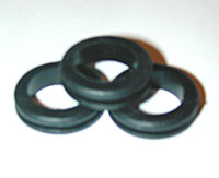 |
Rubber grommets should be used anywhere a cable passes through a hole in a metal enclosure or back box. These will stop the insulation being damaged by sharp edges (not only from movement of the cable during installation, but also from movement caused by vibration or thermal expansion effects in use). | ||||||||||||||||||||||||||||||||||||
| Strain relief sleeves | Sleeving can help protect flexes and cables at any point that they will be subject to stress caused by carrying their own weight from a suspension point, or by externally applied movement. | ||||||||||||||||||||||||||||||||||||
| Glands | When attempting to make a cable entry or exit waterproof, or when working with cables that must be terminated with glands like SWA, glands must be used. These not only fix the cable in place but also offer the water protection required, strain relief and often a facility to connect the cable screen (where present) to earth. | ||||||||||||||||||||||||||||||||||||
| Minimum bend radii | Care must be taken with cables, to not attempt to bend them too acutely, since this may cause damage. Over bending a cable can crack the insulation or strain the conductors, causing the conductor to cut through the insulation.
OK, so how much can we bend a cable? The maximum bend that can be put in a cable is described as the "minimum bend radius" at the inside edge of the cable. A simple way to imagine this is:
So what does this mean in real life? The most common cable for house wiring is BS6242Y, or "Twin and Earth" (it might also be BS6243Y "Triple and Earth in some parts of the lighting or heating systems). Table 4E of the IEE Onsite Guide (17th Edition) states that for thermoplastic PVC cable with circular or circular stranded copper conductors, we may use the following calculation to determine the minimum bend radius:
Note: the "diameter" of a flat cable should be be taken to be the larger of the two sizes.
For SWA cables, the minimum radius is simply 6 x the overall diameter of the cable. If your cable is not listed above, then you will need to refer to the manufacturers' data sheet. |
Labelling and identification
A well labelled installation is one of the signs of a good one! Things like:
- Clear labels on the consumer unit to identify what is protected by each fuse or breaker.
- Identify main switches.
- Make sure earth and equipotential bonding conductors have the "Safety electrical connection - do not remove" tag on them.
- Identify main equipotential bonds (gas, water etc).
- Make sure any wires that are being used in a non obvious way or contrary to the expected use based on their colour, are sleeved with appropriate coloured tape or sleeving. e.g. the switched live returning from a light switch is carried in the black/blue insulated wire, it should be flagged with red/brown at both ends (you will curse the installer, the next time you remove a ceiling rose and then notice no marking on the switch wire!)
- An installation that uses both 'old' (red/black) and 'new' (brown/blue) colour codes must have a warning label affixed to the consumer unit.
Support
Clips
Unless otherwise supported, cables should be supported by clips at regular intervals:
- Horizontal runs - one clip at least every 250mm
- Vertical runs - one clip at least every 400mm.
For horizontal runs, the nail in the clip should be under the cable, not over, to reduce the risk of the cable pulling away from the clip.
Do not stack multiple cables under a single clip - you risk damaging the cable.
Always add a clip as close as reasonably practical to the termination (eg. consumer unit or junction box).
Seventeenth Edition (BS7671 Amendment 3) required the use of sufficient metal cable fixings in escape routes to prevent premature collapse of the cable installation obstructing the escape or fire-fighting route.
Cables on top of metal cable tray, ladder rack or similar, or cables installed within conduit and metallic trunking systems would need no special consideration. Cables embedded in the building are not considered liable to premature collapse, but above a suspended (tile and grid) ceiling they would be.
However, cables clipped to walls and cables inside of plastic trunking where the lid can pop off when there is heat build-up will require fixing in such a way that they will not become an entanglement risk. Wiring systems will need to be secured with something that stops cables falling down if there was a fire. A range of options are available including metal fixings. Mini-trunking (and plastic dado and cornice trunking) could be made compliant by the use of metallic clips attached to the screws which attach them to walls. Plastic conduit may be fixed with steel saddles.
The type of cable fixing must also be suitable for the type and purpose of the cable; for example, additional requirements may apply to fire alarms to BS5839-1; for emergency lighting installed according to BS5266-1; or for cable of life safety and firefighting systems in large buildings installed in accordance with BS8519. The regulation applies to all cables, including television coaxial, door entry, telephone and data networking; not just mains.
There is currently no single standard to which metallic cable fixings must comply. This includes the wallplug or other fixing into the building substrate, although it is considered unlikely that plastic wallplugs or similar would comply.
Note that the Eighteenth Edition Regulation 521.10.202 Highlights the same risk about cables that hang across access and egress routes hindering evacuation and firefighting activities. However the Eighteenth edition regulation does not limit the scope of the requirement for metallic supports to just access routes. This in effect precludes the use of plastic cable clips as the sole means of support for any cables fixed to walls or the underside of other structures anywhere in an installation.
(it notes that "Suitably spaced" steel or copper clips, ties, or saddles are examples of fixings that will meet the specification).
Trunking
Many types of trunking exist - some, like self-adhesive mini trunking are easy to fit (even though it usually falls off the wall shortly afterwards unless you buy a good brand to start with!). Try not to overstuff trunking, otherwise the lid won't go back on.
Under Floors
Under upper floors, cables can simply rest on the ceiling of the room below for support. However, under ground floors of older properties there may be a substantial void beneath the boards. Sometimes it will still be acceptable to allow the cable to lay on the sub floor, however this is not the case if the floor is damp (or likely to become so). You also need to take into account the possibility of rodent damage. If these problems are anticipated, then it is important to support the cable under the joists using clips, trunking etc. Where rodent damage is a known problem, (metal) capping may offer some more protection.
Making good
Once you have installed and tested all your new wiring, there is the rather more mundane task of filling all the holes, and reinstating the fabric of the building before you lose too many household pets or children into floor voids, or incur the wrath of the style police!
Filling chases
Bonding plaster is cheap and easy (old plaster that has been sat about in the bag is ideal for this - it sets much faster). ). Fill just below the surface to allow a final skim of filler or multifinish plaster. If the wall is old and crumbly, then paint some dilute PVA into the chase first, to stop it sucking all the water out of the plaster & to improve adhesion.
Try and avoid getting wet plaster into the back of switches and sockets (or you might find out just how well those RCDs work!)
If the cables keep popping out of the chase, nail some capping over it, or use the occasionally well-positioned wide-headed clout nail (beside the cable, not through it!), or dab of grab adhesive will keep things in place until the plaster has had time to set.
Replacing floor boards
Nail or screw them. If you think they will need to come up again, use screws (they will probably squeak less as well). Where you have had to make cuts that are not over joists, you will need to include additional support. A short length of 2" x 2" screwed to the side of the joist can take the end of a board.
