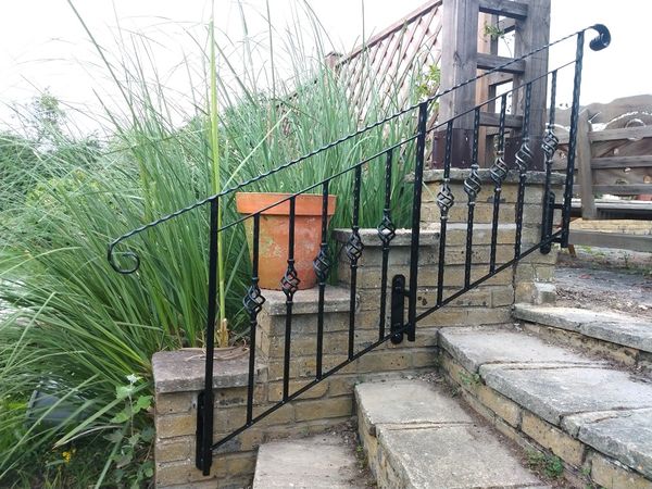
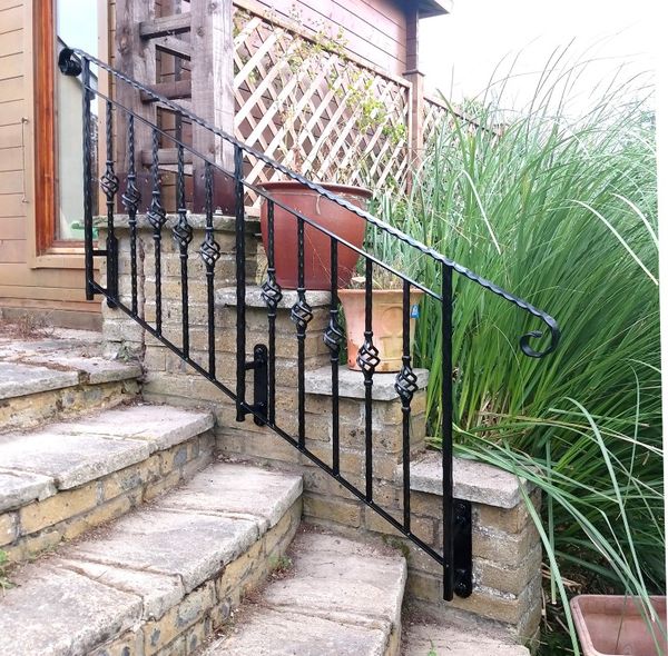
Ornate wrought iron handrails
There are some steps down from the end of our patio leading down onto the lawn. Although only 5 fairly shallow steps, they can be a bit tricky if you are not too sprightly on the pins because they are a bit uneven, and not all treads have the same "rise". So for the sake of the older relatives (and probably us in a few years) I thought it would be sensible to add something to hang onto while navigating the steps.
Previously I had a dabble building some slightly decorative steel handrails for the steps at the front of the house. This time I though I would go with a similar theme, but also try my hand at something a bit more ornate.
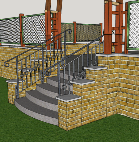
So the first port of call was a sketchup model. The first attempt was perhaps not met with the appreciation that I felt it deserved (the term "scaffolding" was used by my wife!), so I had another go adding some more "frilly" bits:
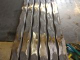
So having got a model and some approximate sizes, I ordered the steel from F. H. Brundle [1]. The balusters were in the "reduced to clear" section, but they had plenty enough for my needs at a good price. I ordered a 6m length of 20mm square hammered bar, some 20 x 5mm flat bar, some 50 x 5mm flat bar, and some 50 x 8mm hammered flat bar for the actual handrail. Plus 4 fancy scroll ends for the handrail.
[1] Actually had to do a second order in the end... We will gloss over the bit where I thought I was being smart ordering some spare balusters in case I needed to adjust the spacing and so may need extras (I did), but I neglected to order enough to do both sides and not just the one side I was focussing on in my model!
Getting Started
So the steps are flanked by reasonably solid walls, but based on my previous experiences with the quality of construction of the patio floor itself, I though fixing them to the walls would be a better bet. This did however introduce a problem that the walls are capped with stones that overhang them a bit, so I needed a way to offset the handrail away from its fixing plate.
So I designed the mounting bracket for the uprights to have a 75mm offset away from the base plate so that the upright would clear the capping stone.
Starting fabrication - mounting plates and uprights
I cut six 250mm lengths of the wide flat bar. and tack welded them into a stack. Then marked out the hole positions and centre punched those. I could then drill through all the plates in one go. I put a radius on the ends in a similar way, chopping off the corners with the cut off saw, and grinding into a nice half round shape with a 40 grit flap disk on an angle grinder. Grinding off the tack weld finally separated them into the individual plates.
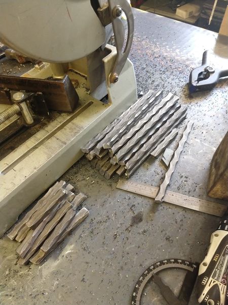
Next we needed the offset pieces - twelve in all at 75mm long. So I cut off a chunk of the 20mm hammered bar to make all of those. I ground a heavy bevel on all of the ends so that there was plenty of space to weld in while leaving the ability to grind it flush after without it also falling to bits!
The remaining 20mm rod, I cut into six equal lengths that would have to be tall enough for the final result. (we do have some mounting height wiggle room to help out)
- Building the brackets and uprights
Installation and assembly
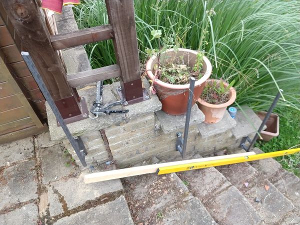
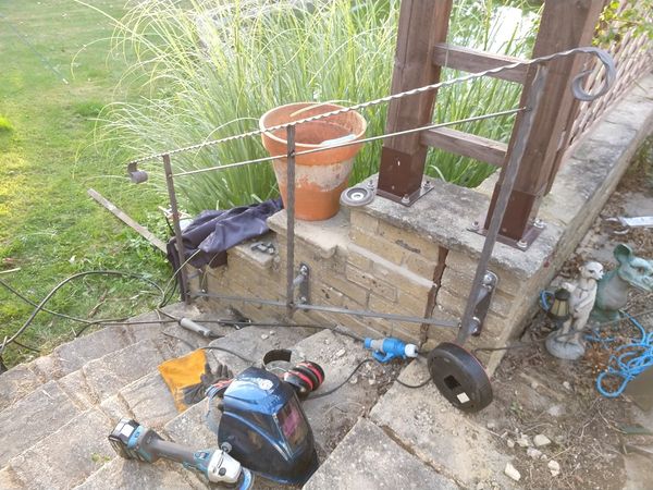
Now ideally one will do the rest of the fabrication with each bit assembled on a decent flat assembly surface in the workshop. However the problem with this is some of the design needed to be tried out first to come to the final sizes since the steps are not all equal in rise or going, and finding the best overall angle for the rail, and height above the centre line of the tread line needed a bit of experimentation. So I decided to fix the first and last uprights in place first. Then I could work out the position of the centre one, and also the angle and height of the handrail by clamping a stick to the uprights to find a position that "felt" right.
Fixing the uprights
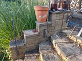
Each upright was fixed using the 12mm holes in the base plate. I drilled the wall with my SDS drill and a 14 mm bit, and put a 200 mm length of 12mm threaded rod to use as fixings, setting each of these in the drilled holes using Fischer VL300 Resin (just pump in 4 or five squirts from the mastic gun and push the rod in, twiddle it round a bit to distribute the resin, and leave it alone. 5 mins later it will be fixed! (work time and full cure time depends on temperature - since it was a warm day, it was workable for 4 or 5 mins and fully cured in an hour. (the cartridge nozzel mixes only what is needed as you squeeze it out of the tube).
Trimming the uprights
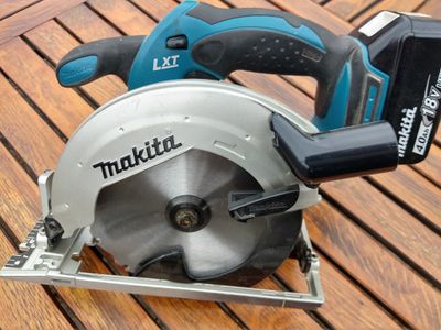
Once I knew the angle of the handrail, I could mark the angle to cut on the top of each upright. I tried a new approach with a carbide metal cutting circular saw blade in my 18V circular saw. That worked really well and made sure that the cuts were square in the non angled cut direction - something that would have been less accurate if I had cut off the tops freehand with a grinder.
The handrail
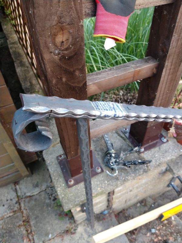
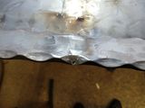
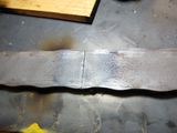
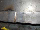
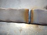
The next job was to prepare and fix the handrail. I had a three metre length of this, and each side needed to be about 1.8m long. The more numerate might spot the problem here. However I also had 4 decorative "ends", and each of these is on the end of a 400mm length of hammered flat bar. So in reality with a couple of nice full penetration welds between a pair of bevelled joins, it was easy enough to get the required length. A bit of touching up with the flap disk to put the scollops of the hammered edges back where they belong. Once this was joined, I could test fit and decide where to position it. It wanted a bit more overhang at the bottom (since the steps curve out there, and less at the top where the is more danger you might walk into the end of it).
- Joining the handrail to its ends
Once this was decided I marked the position of each upright and took it back to the workshop to drill 12mm holes at each upright position. I could the "plug weld" down through the hole into the top of the upright, and fill the hole as I went. Once ground off and painted you can't see where the hole was.
Infill panels
The balusters were to be inserted as a couple of panels set down a bit from the handrail (so there is plenty of space to grip the rail without frequent obstructions to your fingers from the balusters). So fixing in the top and bottom flat bar rails for this was the next job. These needed carefully trimming to the right length so that they met the uprights at the right angles. Once the first one was tacked in place, the second top section was done so that it nicely "flowed through" the mid span upright. The bottom section wanted to be parallel to the top, so I cut a storey stick to set the offset from the top rail, and used that for setting the position of the top and bottom baluster rails.
Spacing
Working out the spacing was way more effort that it ought to have been. It gets complicated by the spacing being set by the guideline for building regs of no more than 100mm of gap between uprights in the horizontal plane, but the fixing is to an inclined plane. Also don't forget that the baluster itself is actually 14mm wide and not the infinitely narrow line that looks good on the diagram. In the end I found that the best approach was to measure the horizontal gap between uprights Estimate the number of balusters you will need, and subtract that multiplied by their thickness from that gap. Now divide that remaining space by one more than the number of balusters (you will have one more space than baluster).
So in my case it was, measure, take off 70 mm (14mm x five balusters), then divide what was left into 6 equal pieces. Now cut a bit of wood to the length of that space, and use it to set the horizontal spacing of the balusters.
Fixing balusters
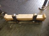
I started by cutting the tops off all the balusters to the right angle an to the same length on the cut off saw. The using my spacer, tack welded the top of the baluster, leaving the bottom unfixed for now. Rinse and repeat until all the tops are tacked in place. Now the vertical height of each ought to be exactly the same, however allowing for slight variations made thus far, that is not a sure bet. They will look right since all the tops were cut off equal, but each bottom needs to be trimmed in place. I knocked up a small jig from an offcut of 50 mm flat bar that I could use to guide the angle grinder and find exactly the right length. I then fixed the bottoms of each baluster using a (magnetic) spirit level to make sure each was plumb. A quick lick with a flap disk in the angle grinder taking care of any slight imperfections in length.
- Fitting the balusters
Finishing fabrication
Last job was to spot any gaps and fill those with weld or two part filler, and do a final bit of touching up of weld spatter, and making the odd ugly weld less ugly with the grinder, Then we are ready for paint
.
Painting
For this I used smooth Hammerite in black. Since some of the metal stock felt a bit greasy in places, I wiped down everything with acetone first. Then applied some bits with a brush, but most of it with a very small roller (approx 50mm wide). This makes easy work of getting paint on the underside and backs of all the posts and rails. The decorative baskets on each baluster however are a pain to paint!
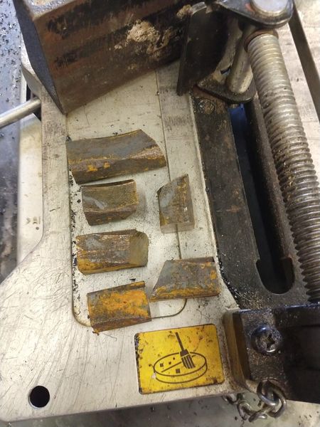
Leftovers
Conclusions
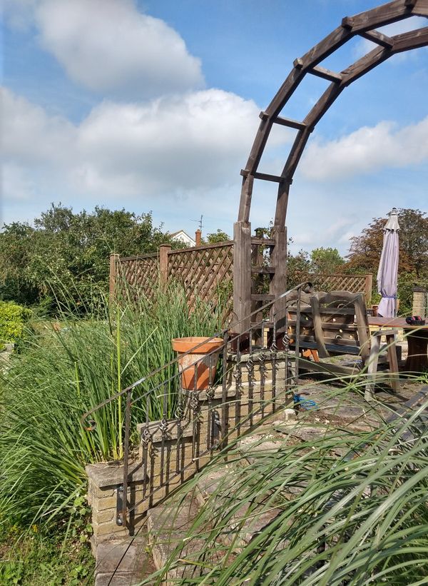
All worked out quite well and they don't seem to get too hot in the sun. A bit of a pain to paint though - especially the twiddly bits!
Total cost of materials and consumables about £260 inc delivery.
