Difference between revisions of "Electronics repair"
m (more) |
(→Diagnosis: Add pics) |
||
| Line 32: | Line 32: | ||
====Diagnosis==== | ====Diagnosis==== | ||
| − | In some cases a visual inspection is all that is required to spot problem components. Look for signs of the top of the case bulging, or appearing dome shaped. Any sign of leakage around the top or base. Or a component lifting from its base. If there is a row of similar devices, check thy all appear to be in-line, and the same height. If any of these faults are visible, then you can assume that even if not totally dead yet, they are not far from it. | + | In some cases a visual inspection is all that is required to spot problem components. Look for signs of the top of the case bulging, or appearing dome shaped. |
| + | |||
| + | '''Failing CAP showing deformation and leakage from the top''' | ||
| + | |||
| + | [[image:FailingCaps1.jpg|640px]] | ||
| + | |||
| + | Any sign of leakage around the top or base. Or a component lifting from its base. If there is a row of similar devices, check thy all appear to be in-line, and the same height. If any of these faults are visible, then you can assume that even if not totally dead yet, they are not far from it. | ||
| + | |||
| + | '''Failed cap with base plug pushed out''' | ||
| + | |||
| + | [[image:CapBulgingBottomPlug.jpg|640px]] | ||
A very useful piece of test equipment for these devices is the Equivalent Series Resistance (ESR meter). These are rather specialised and are often dedicated to the one task, but they can give a very important reading of the overall health of a capacitor, that a reading of its capacitance alone will not give you. Often they can also be used on a device that is in circuit, meaning one can test devices without needing to remove them from the board first in many cases. | A very useful piece of test equipment for these devices is the Equivalent Series Resistance (ESR meter). These are rather specialised and are often dedicated to the one task, but they can give a very important reading of the overall health of a capacitor, that a reading of its capacitance alone will not give you. Often they can also be used on a device that is in circuit, meaning one can test devices without needing to remove them from the board first in many cases. | ||
| + | |||
| + | [[image:ESRMeterTestingCap.jpg|640px]] | ||
Passive component testers (aka LCR testers) are also useful. | Passive component testers (aka LCR testers) are also useful. | ||
| + | |||
| + | '''Example of a failed cap which should have 2200uF of capacitance showing in effect none:''' | ||
| + | |||
| + | [[image:LCRMeterTestingCap.jpg|640px]] | ||
Many multimeters are also capable of reading larger values of capacitance - sometimes using one of the resistance ranges. Older analogue meters can be very useful since the characteristic "flick up" and decaying return of the needle as the capacitor charges up are good visual check on the functioning of the device. | Many multimeters are also capable of reading larger values of capacitance - sometimes using one of the resistance ranges. Older analogue meters can be very useful since the characteristic "flick up" and decaying return of the needle as the capacitor charges up are good visual check on the functioning of the device. | ||
Revision as of 17:39, 23 April 2012
Very much under construction!
This is an introductory article on the repair of electronic items. While this is a broad and deep subject, this article aims to give some basic information that ought to get many failed electronic items up and running again.
Introduction
At one time there were an army of TV repair businesses and others that specialised in repair of electronic items. Alas due to the progress of technology, many of our electronic items have become far more sophisticated, and far more difficult to successfully diagnose and fix - especially without access to detailed technical information and elaborate test equipment. This coupled with ever lower prices for new equipment has resulted in the demise in large sections of the repair industry, and encouraged a "bin and replace" attitude among consumers. Unfortunately this often means that quite serviceable items with only minor faults are replaced when in reality replacement of a few discrete components often costing no more than pennies or just a few pounds would restore full operation.
Common Failures
Capacitors
Probably the single most common failure associated with modern digital electronics is that resulting from failed electrolytic capacitors, and in particular, failed capacitors in the power supply circuitry.
As these components age and begin to fail, they typically start to lose their capacitance, and this in turn tends to mean that power supply voltages either drift out of specified tolerance, or start to acquire excessive electrical noise or voltage ripple. Either of these will impair the operation of circuits powered by these supplies - often to the point of preventing something operating altogether.
Common failures of:
- LCD back lights in monitors and flat panel LCD TVs
- Power supplies for many modern bits of computer equipment, resulting in complete failure, or crashes and other unpredictable operation
- Power regulation circuitry on motherboards in computers, causing random reboots with no warning, system freezes, or simply a failure to start altogether.
- Power supplies in set top boxes, personal video recorders and other AV gear, causing random or unpredicted behaviour, missed recordings etc.
Can frequently be attributed to failing capacitors.
Diagnosis
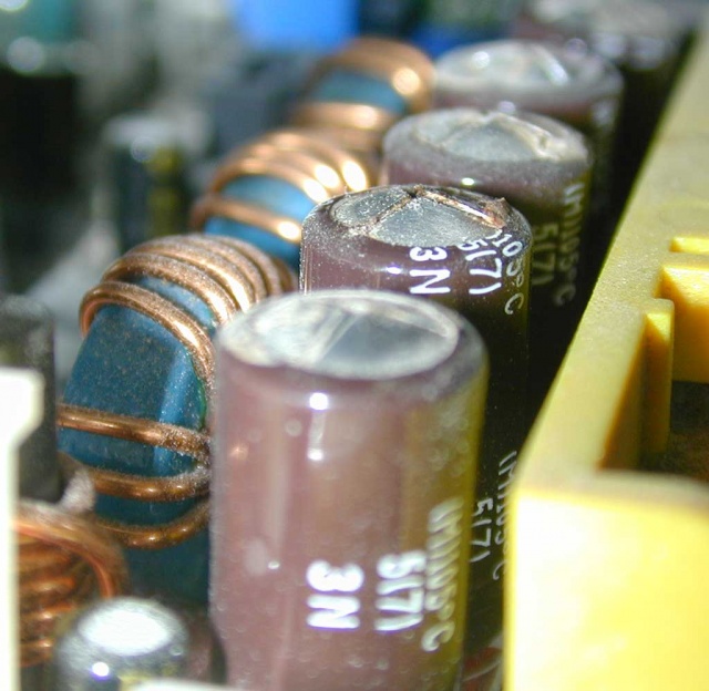
In some cases a visual inspection is all that is required to spot problem components. Look for signs of the top of the case bulging, or appearing dome shaped.
Failing CAP showing deformation and leakage from the top
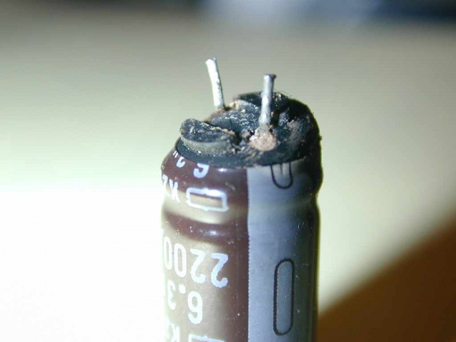
Any sign of leakage around the top or base. Or a component lifting from its base. If there is a row of similar devices, check thy all appear to be in-line, and the same height. If any of these faults are visible, then you can assume that even if not totally dead yet, they are not far from it.
Failed cap with base plug pushed out
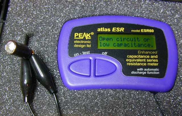
A very useful piece of test equipment for these devices is the Equivalent Series Resistance (ESR meter). These are rather specialised and are often dedicated to the one task, but they can give a very important reading of the overall health of a capacitor, that a reading of its capacitance alone will not give you. Often they can also be used on a device that is in circuit, meaning one can test devices without needing to remove them from the board first in many cases.
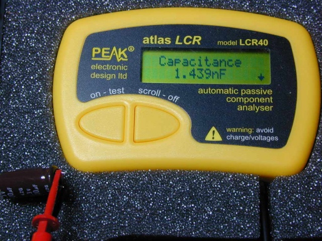
Passive component testers (aka LCR testers) are also useful.
Example of a failed cap which should have 2200uF of capacitance showing in effect none:
Many multimeters are also capable of reading larger values of capacitance - sometimes using one of the resistance ranges. Older analogue meters can be very useful since the characteristic "flick up" and decaying return of the needle as the capacitor charges up are good visual check on the functioning of the device.
In the absence of any test equipment or visible evidence, one can just go on the "replace anyway" principle. The parts are cheap, and sometimes its easier to just replace any likely candidates first and ask questions later!
Repair
Repair is simply a case of removing the existing device and substituting a similar one. When working on power supply circuits it is worthwhile choosing a good quality capacitor designed for "high ripple" operation and low ESR. Also look for one with a long quoted lifetime. Many of the better devices are quoted with a life of 10,000 hours. Some of the cheap ones are only good for 1,500 hours. For devices that stay powered and run for a long time (PVS, set top boxes), this limited life can soon be swallowed in 18 months normal use.
Ideally one should replace a device with one of the same voltage and capacitance. There is no harm is using a device with a higher voltage rating usually, although the higher voltage devices may be physically bigger. If you can't find the exact capacitance, then in power supply circuits it is usually better to opt for larger values.
Component replacement procedure
Typically component replacement will require that the equipment be disconnected from the mains, and stripped down enough to allow the offending circuit board to be removed for service.
Having identified the components to replace it is worth noting (or photographing) their orientation to make sure you get the new ones back in the right way around. (sometimes there will be a silk screened overlay on the board that will identify polarities and component numbers etc.
Desoldering
The principle of desoldering is simple, either heat up the solder so that it melts, and then suck or mop it up while still liquid, or, simply remove the component while the solder is liquid. The practical reality can be somewhat more of a challenge! Even assuming that you can remove most of the solder, it only takes a slight residue to keep a component firmly attached to a board. The desire is to remove the device without doing any damage to the circuit board (damaging the device itself in the process may be a price worth paying in many cases - especially as in most cases it will be defective anyway since that is why you are replacing it!)
The difficulty comes with multi leaded devices, and with more sophisticated circuit boards. Simple passive components with two or three leads are usually easier to remove - since you can often free one lead at a time. Multi lead devices are more challenging since its more difficult to melt all the connections at once. This often forces the use of solder removal techniques.
The simplest PCB to desolder from is a single sided one with tracks on only one side. Double sided boards with plated through holes are somewhat harder to desolder through hole mounted components from since solder can lurk on both sides of the pin and also through the hole in the board.
The hardest boards are multilayer ones as used in modern items with very high component integration densities like computers and other IT kit. Here the board design may often have heavy copper power and ground plane layers sandwiched inside. These conduct the heat away from your soldering iron making reflowing the solder difficult.
Equipment
- Soldering irons suited to desoldering usually have more power and bigger heavier tips fitted than those ideal for soldeing.
- Solder suckers are very useful for clearing most of the solder from a joint.
- Solder wick or braid can be very useful for cleaning remaining solder from a PCB once the component has been removed (very good on surface mount boards)
- Some liquid or paste flux is often handy to help the solder flow and make cleanup and removal simpler (especially with the wick / braid)
More specialist kit includes:
- desolder stations (big powerful soldering irons attached to a vacuum pump of some sort).
- Hot air solder stations (ideal for heating wider areas of a board at once soldering or desoldering multi lead devices in one hit)
Techniques
Small components with only a couple of connections can often be removed simply by melting the solder with a suitable iron, and pulling the device from the board while keeping the heat on. Take care not to apply too much force (especially force that would tend to push the solder pad away from the board surface)
Sometimes if the leads of the device are visible, cutting them to free the device is preferable, since the individual wires can be much simpler to remove individually. This can even work for surface mounted ICs with many visible legs. A sharp knife can be run down each side s few times to cut through the legs, and then each one individually flicked off with a hot iron.
In some cases, removing all the solder with a desolder tool will allow the component to be freed and removed (a gentle wiggle is sometimes needed to break the last grip of the remaining solder)
On multilayer circuit boards with through hole devices (like capacitors on a PC motherboard in the power regulator section) it can be very difficult to get enough heat onto the joints to reflow the solder - this is because the devices are often connected to heavy power planes on one of the inner "vias" on the board, and these suck the heat away too quickly. Hear hot air solutions can work well since they can be used to preheat the surrounding area of the board and allow the area in question to be heated enough to melt the solder.
Modern electronics also tend to use lead free solder. This is not only more problematic from a reliability point of view, it also needs a higher temperature to melt properly.


