Backup power, Installing a transfer switch
In this article we are going to look at how you can provision your house to accept backup power from a generator in a safe and convenient way.
Small portable petrol and diesel generators are handy things to have, allowing mains powered appliances to be run anywhere, even if nowhere near a mains supply. They can also be a way to keep you house or business operational when experiencing a power interruption.
Using generator power in the home
There are a number of ways you can use a generator to power your home, but installing a transfer switch will allow:
- A clean tidy install using all the existing house wiring without need for extra extension leads
- The ability to power "hard wired" things like your central heating system
- No danger of back feeding the local electrical grid which at best will overload your generator, and at worst might electrocute someone working on the power grid!
Transfer Switch
One safe way to make a connection between properties electrical system and a generator is using a "Transfer Switch" (also known as a "changeover switch", or "break before make switch").
A transfer switch does two things: it disconnects the house grid connection, and it connects the generator feed to the house consumer unit(s). Most importantly, it does this in a strict sequence - disconnecting one supply before connecting another. It is impossible to have both supplies connected at once.
Transfers switches can be manual or automatic. Automatic switches are usually only found in industrial settings with permanently installed backup generators.
For the purposes of this article we will focus on manual start generators, and manual transfer switches.
Considerations before you start
Choice of generator: you will ideally want an inverter generator. These are more suitable for powering sensitive electronic equipment since they use an inverter to synthesize a clean mains supply, and are far less likely to inject unwanted spikes or other disruptions into the supply.
You will need to pay careful attention to earthing and circuit protection. Most properties will have an earth connection supplied by your electrical distributor. However power interruptions can happen for any number of reasons, and so it is not safe to assume that the earth system will be functional when there is a power cut. This means that your house will need a functional earthing system in addition to the distributors earth connection. Houses with TT earthing systems are the easiest to connect, since they are basically ready to go.
The problem comes with the more typical TN-S and TN-C-S earthing systems. It is permissible to connect your own local TT earth in addition to the supplied one (see the TT Earthing article on this), but that may not be all that needs to be done. A modern install which already includes RCD protection for all circuits (either via a 17th edition split load CU with multiple RCDs, or and all RCBO consumer unit), will also be ready for a generator supply.
Older (16th edition or before) consumer unit installs which have some circuits that do not have any RCD protection are more tricky, since the impedance of the TT earth may not be low enough to reliably trip a MCB or blow a fuse in the event of an Earth Fault. In these cases, the best solution would be to upgrade the CU to a modern standard. Or, since this is a special "infrequent use" scenario, adding an additional dedicated RCD in the generator connection to the transfer switch. (this will offer the protection required, but in the event of a fault will disconnect all power from the generator).
Lastly, you will probably need to make sure that the generator has an earth connection itself, and that its neutral output is tied to earth. (normally a generator will produce an output where the two terminals are 230V separated, but the whole supply is "floating" with no reference to real earth potential. This can cause problems with electrical systems that expect the neutral to be at the same potential as earth. (some boilers will use "flame rectification" to sense when the burner is lit, and so may not fire and operate correctly without a proper earth reference. Some EV "granny lead" chargers will also expect to see a neutral earth bond before allowing vehicle charging).
Example installation
What follows is an example installation of a transfer switch into a property with a TT earthing system. The plan is to:
- install an exterior connector in place where it will be easy to site and connect a generator.
- Wire this connector to the location of the existing consumer units.
- Install a transfer switch, and connect its output to the consumer units,
- and finally, connect the generator input and the house mains supply input to the switch.
External input connection
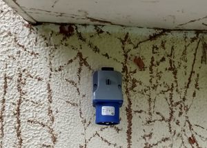
For this I selected a MK Commando 32A surface "inlet" connector. This is in effect a surface mounting "plug" rather than a socket - so the live end of the lead from the generator will not have exposed live pins! The 32A rating is more than adequate for the current generator, but would support an input of 7.2kW if required. This was mounted on an outside wall in a place that is also partly under cover (the connector is rated as IP44, so can safely be rained on, but try not to hose it or immerse it in water). The wall chosen is also at the end of the cupboard that contains the consumer unit, so a hole could be drilled straight through into the cupboard. From there I wired a dedicated feed in 4mm² Twin & Earth back to the electrical installation.
Choose a location for the switch
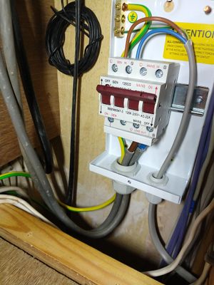
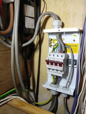
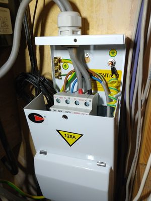
The next job was to find a place to locate the switch. The switch chosen - a 125A changeover switch by Lewdenis fairly large (which is good, since it allows plenty of space to wrestle 25mm² meter tails into it) could only really go in one of two locations.
The small amount of space on the distribution board would be usable, but would require the existing main switch and service connector block to be moved up to give enough headroom (since the cable glands on the transfer switch enclosure will add some extra height to it).
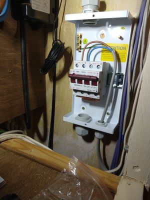
So in the end I elected to go for a spare space on the side wall near the main cut out, taking care to position it so that it won't interfere with access to the main supply fuse, or removing the cover of the cut out.
Connecting the output tails to the switch
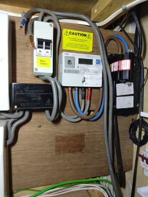
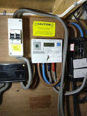
This install has multiple CUs but there is also a single standalone "main switch" that is in circuit between the electric meter and the service connection block where the feeds to the CUs split off. This means there is a single point of isolation for all CUs. To retain this functionality, the transfer switch needs to be inserted in the chain before this main switch.
The next job is to connect some 25mm² tails to the output of the switch, and dress these round the installation so that they run to the main switch.
Connect an earth to the transfer switch enclosure
The transfer switch is enclosed in a metal box, and so that needs to be connected to earth. Hence a wire is connected back to the installations main earth terminal while we are installing the output tails.
Do the final tails connections
So far all the work a has been done before anything is connected to the installation. Now we need to make the final connections by moving the meter tails from the main switch to the transfer switch, and connecting the output tails of the transfer switch back to the main switch.
Testing
Now is a good time to test all the new installation before anything is connected to the rest of the system. Check the function of the changeover switch. Check the resistance of all the connections, and do an insulation resistance check of all the new work.
So now we need to power down the house electrical system. Since we also need to work with the live meter tails before they connect to the main switch, we also need to pull the main cut out fuse.
Now we can move the meter tails to the main input connection points on the transfer switch, and connect the waiting output tails from the transfer switch back into the main switch.
Final Checks
Once all connections have been inspected and checked for tightness, we can replace the cover on the main switch. Fit the earth fly lead that connects the cover of the transfer switch to the main box, and screw the lid on, and finally replace and reseal the main cut out fuse.
Using the switch
Depending on the output power of your generator, it is likely that is is not capable of running the whole property at full load. So some planning is required to identify which loads in the house need to be turned off before moving the load to the generator. Sometimes this will mean turning off an individual appliance, but it can also mean turning off a some complete circuits.
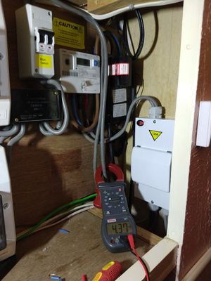
You can do some preparation in advance by assessing or measuring the loads from various circuits.
When a power cut happens, it is often then easier to turn off the house at the main switch, and move the transfer switch to the generator position. Connect the generator to the external input socket, and make sure its neutral connection is earthed. Then start the generator and wait for it to indicate is has reached a stable output). Lastly turn back on the main switch in the house, and turn on the circuits that you plan to support on the generator.
When power is restored, one can use the transfer switch to return the loads to the mains. Once this is done the generator can be stopped.
Knowing when the power cut is over
One slight irony of having you own power backup that is fully isolated from the supply, is that you need to be able to tell when the mains supply has been restored. For properties with relatively modern electronic electric meters, one can often use the illumination of the display on the meter itself to indicate there is power available on the mains. Alternatively you may be able observe neighbours or street lights etc as an indication.
In cases where this is difficult, you can fit a neon indicator into the transfer switch enclosure to show when the mains input is live. Alternatively see this DIY Mains power restored alarm gadget.
