Mains power restored alarm, non contact
If you have installed a transfer switch and have access to a backup power source such as a generator or a battery bank and mains inverter, then you can safely switch power for the whole property between a grid supply, and your backup source. The transfer switch does this safely by ensuring the power transfer is "break before make" - forcing the disconnection of one source before the other can connect. This ensures there is no danger of your local power source attempting to back feed the grid supply - something that at best would overload your local generation capability, and at worst could kill or injure someone working on the grid supply.
One shortcoming of using a transfer switch is that once the grid connection is disconnected, how can you tell when the power cut is over? This article explores a small project to make identifying when the grid mains power is restored, easy!
Detecting mains power
When operating from your own power source, typically all of your installation is disconnected from the grid supply, and so checking if it is working again is more complicated than just plugging something in, or turning on a light. If you have an electronic electricity meter which has an integral LCD display, you may be able to see when grid power is "on" because the display will be functioning. However this is something you need to go actually "look at" to see. It would be nicer to have some kind of audible alarm that notify you when the power comes back.
Direct connection
One way to detect power is to make a direct connection to the incoming grid supply terminals on your transfer switch, since these will go live whenever the grid supply is working even if you are not currently switched to that supply. The difficulty here is that these terminals are typically before all of your local circuit protection such as the fuses or circuit breakers in your consumer unit. The only protection available here is that provided by your main incomer fuse (typically at 60A or 100A). Connecting to that typically requires meter tail sized conductors (usually 16mm² or 25mm² cables). So to safely make connection here, you would need a set of tails to feed a dedicated small CU containing a MCB or RCBO that you can then feed a circuit from to power your detector. Lots of extra complexity and expense. Alternatively you could install a simple neon indicator on the understanding that it is very low risk, but again you then have something that needs looking at periodically.
Non contact connection
If one can detect mains presence without making direct contact, this all gets simpler. Non contact power detection can be done by inductive or capacitive coupling to a live wire. Inductive coupling (often using a current transformer with a coil placed around a wire) can detect when current flows in that wire. However we can't use that here since there will be no load on the supply wiring at this point, and so no current flow to detect.
Capacitive coupling however will work, since this will allow the presence of a voltage to be detected even when there is no current flow. This is the same principle used by commercial "volt stick" style detectors. (in fact if you have one of these that can run for hours and not automatically turn off, and then spring into life and beep at you when the power comes back on, you can stop reading the rest of this page now!)
Non contact capacitive coupling - theory of operation
Whenever you place two isolated conductors in close proximity, any voltage applied to one will tend to cause an accumulation of electric charge on it, and that in turn will result in an opposing electrical charge accumulating on the other nearby conductor, forming a capacitor. This accumulation of charge on one side of the capacitor will briefly allow a current to flow into it as it "charges". However once charged, that current flow stops. You can however allow the charge to flow out again, so you will see a reverse flow of current as the capacitor discharges. While a steady direct current can't flow past a capacitor, alternating current can - since the continuous reversals of current flow direction can repeatedly charge and discharge the capacitor.
Proper capacitors have conductive plates with a large surface area separated by a very small distance, with a "dielectric" insulator placed between them to increase their effective capacitance. However two wires close to each other will also exhibit a capacitance, but due to the very small surface area of the "plates" the capacitance will be tiny (typically a few pico farads, where a pico farad is millionth of a millionth of a farad!) The upshot of this is that you can only draw a very very small current out of this capacitor, and that makes detecting it a little more difficult.
To be able to able to detect and use this coupled voltage, we need to amplify it massively first.
Design
Prototype 1
The simplest form of electronic amplifier is a transistor. This electronic component behaves like an electrically controlled "valve", where if you allow current to flow in one of the wires, and it will progressively "turn on", allowing a current to flow between the other two wires. Crucially however a very small current flow in this "base" control wire, can allow a much larger current flow (could be several hundred times more) between the other two "collector" and "emitter" wires.
One transistor alone however is not going to have enough amplification or "gain" to cope with our tiny signal. So one way to get substantially more gain is to use a configuration known as a "Darlington pair". Here one transistor is used to boost a signal, which is then used to drive a second transistor which boosts it again. Like this the gains each of the transistors are in effect multiplied together. So if one transistor can make a signal 100 times bigger, then next makes that 100 times bigger again, or 10,000 times more altogether.
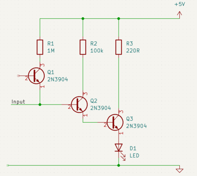
So I built a prototype using some common NPN transistors configured as a Darlington pair, with one additional transistor just used as a final "switch" to turn a LED on.
The theory of operation is the input is connected to a sense wire or plate that is placed near to the mains voltage carrying wire. In each half cycle when the voltage reaches high enough to "turn on" the first transistor, that turns on the next, and that will then fully turn on the final transistor. Switching on the LED. The LED will in effect blink at mains frequency, but that is fast enough that it will appear to be "on" to the eye.
If one were to look at the voltage at the bottom of R3, you would see 5V any time Q3 is off, and then it will fall as the transistor turns on and current flows though it a voltage drop will appear across R3, and the voltage you see will fall.
If you replaced the LED with some form of buzzer, then you could get this circuit to give an audible indication of a mains voltage.
Prototype 2
Experimentation found that this circuit worked, but was not very selective. Sometimes being way too sensitive, and other times not enough (it turns out there was an added complication that I became aware of later!)
Looking in the parts bin for something else to try as a detector, I found the venerable 555 timer IC. These highly versatile devices can be used in all sorts of ways as detectors, counters and timers, just by choosing how they are wired up and by the selection of the discrete components you connect them up to. For this application, the "trigger" input of the device could be connected to the sense wire, as it is in effect connected to a very sensitive comparator circuit, which can "turn on" the IC when a voltage is sensed on the pin that is high enough to trigger the comparator - something it will be every half mains cycle. Some people use these are non contact voltage detectors since the timer output can be used to drive a speaker or sounder directly to create an audible "buzz".
Odd results
Testing the new circuit showed it was "better" than the first one, but was still not giving the results I expected, and it was quite difficult to nail down what was wrong. Half the time it would trigger even if nowhere near a mains lead, or fail to detect being right next to it.
Eventually the thought occurred to be to wonder why commercial non contact voltage detectors work so well, but this one was not working like I wanted? So for a comparison, I grabbed my multimeter that also includes a non contact voltage detection capability, and waved that close to my detector just to see how that performed. Much to my surprise it lit up like a Christmas tree anywhere near my workbench. In fact it appeared that the whole bench was "live" even when not near any obvious mains leads (quite an achievement for something made mostly from veneered chipboard!).
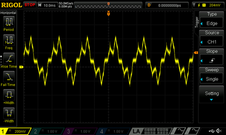
Presumably this was a result of being close to too much electrical and electronic kit, lights, and USB leads etc (Some USB power supplies have "questionable" switched mode power supplies at their end!) The signal I was looking for was just being lost in the noise.
Now I realised why I was having a hard time, just moving the circuit to the other desk a couple of feet away was enough to make it all work as expected!
Snazzing it up
So having a working circuit on a breadboard, I though now would be a good time to add in a micro controller! This would allow me to do more sophisticated detection, and create some more "crafted" audio alerts, rather than just a continuous buzz.
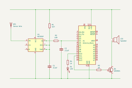
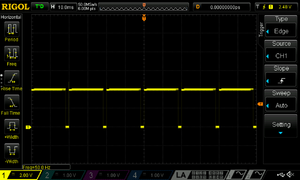
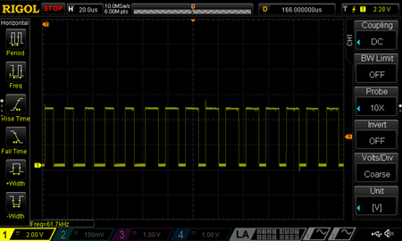
Taking the output of the 555 into a digital pin on the Arduino let it read the state of the detector. Fiddling with the size of C1 allowed the mark space ratio of the clock pulse generated to be "tuned" to be mostly mark. This would ensure that the processor would read it as "high" most of the time when it looked.
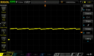
Just to make sure that it always saw a proper high logic level when triggered I added R2 and C2 as smoothing element.
Hooking up a piezo sounder to a digital output pin, allowed simple tones to be generated by feeding a square wave to the pin. The Arduino library includes a "tone" function that uses one of the internal timers to drive a pin at a configurable frequency.
By messing about with this, I could create a little tone sequence that was designed to be disturbing enough to hear and recognise, but hopefully not too irritating.
Introducing a delay of 30 seconds after the tone is played, also stopped it being a continuous noise, while still being a repeating reminder.
Louder
That worked ok, but could do with a bit more volume than the small sounder could manage. So I thought I would try a small loud speaker that was floating around having been taken out of an old computer case. I did not want to drive this directly from the Arduino pin since these can only source 40mA maximum, and also a speaker is an inductive load that will tend to generate nasty back voltages when driven with a square wave. So I slapped in a transistor Q1 to act as a buffer. That made a more impressive noise....
Talk to me
This was all good, but it was still not "speaking to me".... then it occurred to me it might be nice if it actually did speak to me! A spoken alert could also explain to someone not aware of the meaning of the alarm, what it was chirping about.
Arduinos don't have a built in Digital to Analogue (DAC) converter, so one can't simply feed sample data into that to get sound. However they can produce Pulse Width Modulated (PWM) outputs, which are often used for control applications like changing motor speeds or lamp brightness. If one sets up a PWM output to send a highish frequency clock to a pin, and then lobs sample data at this to dynamically set the pulse width in sympathy with the magnitude of the samples, a speaker aught to turn this digital binary mess into an approximation of digitised audio.
There is a PCM library available in the library repository that does just this. It uses one timer to generate a PWM output to a pin, and then setup another timer to generate a 8Khz interrupt. The interrupt handler can then feed sample data in to control the PWM pin. All you need is mono sample data, call a function to kick off the process, and it will then playback the sample asynchronously in the background!
Need words
Now an Arduino nano only has 32KB of flash memory, which is not much recording time - especially if at CD quality. However if you knock down each sample to 8 bit mono, and the sample rate to 8000 samples per second, you can fit in a few seconds of audio if you have nothing much else you need to store in the internal flash. (you could interface an external SD card if you needed lots of playback time).
So I recorded myself saying "Mains power is back on", in Audacity. Changed the format to PCM, and the sample rate to 8000/sec, then I saved that to a .mp3 file.
The PCM library included a Java executable that can load a mp3 file, and turn it into a long string of sampled digits in the form of "125, 123, 120, 115, 111, 105, 100, 95, 92, 93, 95, 97, 99, 98, 98, 103, 111, 120, 126, 132, 136, 137, 138, 140, 144, 147, 148, 147, 145, 142, 137, 136, 137, 137, 134, 132, 130, 127, 127, 128, 126, 124, 122, 119, 118, 116, 117, 120, 121, 121, 121, 121, 122, 125, 130, 134, 135, 136, 137, 137, 138, 140, 142, 142, 143".
My 3 second audio clip was thus turned into about 650 lines of text. This could then be #included into my Arduino sketch as an array to store in flash memory.
(altogether, the total code and sample data used about half of the available storage on my Arduino nano clone)
Putting it together
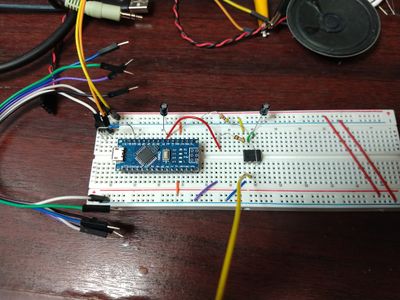
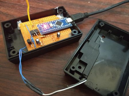
Now I had a working prototype and some code to go with it, it was time to make it look pretty. I had a spare small project box and some lengths of copper strip board (not quite your veroboard of old, but with a layout of tracks more suited to mounting DIL packaged ICs), so I cut off slightly too little of that (it turned out an extra couple of rows would have been nice to avoid the rather bodgy looking R1 having to fly over the top of the 555!)
The next problem was that the small round speaker I was using for test purposes was bigger than the box. So I needed a smaller one. Fortunately a visit to the pile of scrapped laptops "for spares" that I have laying about yielded a small speaker enclose in a tiny case, so I snipped off the extra bits of case and the mounting holes that would not fit the box, and glued that into the lid (having hacked out a sound hole in it).
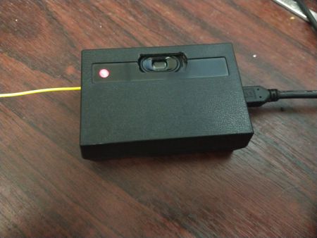
Since there was a hole in the box designed to take a 5mm LED, it seemed churlish not to use it, well that and SWMBO complained that it did not have an exterior light! My protestation that I had used the tiny on board LED that you could just about see if you squinted through the hole at the right angle, did not meet the appreciation I had hoped for (one of the pitfalls of marrying an engineer, is she knows lazy design when she sees it!). So I added R4 and D1 to give a slightly under driven red LED on the outside of the box, and hooked that up to pin 13 on the Arduino that is also connected to the on board LED on the nano.
Operation
In use it is run from a USB phone charger power supply, and the unit positioned close to the incomer fuse and the electric meter. It will then sit silently waiting to detect mains voltage, so it can let you know you can switch back to mains and turn off your generator.
Code
Here is the source of the sketch:
/**
 * Voltage Detector audio alert module
 *
 * This is a small project to detect the output from a non contact voltage sensing
 * circuit and produce an audio alert.
 *
 * When running an electrical system from local power, this alarm is used to
 * alert when mains power is available again. Using a microcontroller to produce
 * the alert allows more control over the sound of the alert, and also the repetition
 * frequency, so that the alert is noticeable, but not too irritating!
 *
 * Version History
 * ===============
 * V 1.0    Nov 2022    J Rumm    First release
 *
 */

#include <PCM.h>

#define ONE_SECOND     1000
#define DETECT_INPUT   4
#define SPEAKER        11

// Note the speaker pin is hard coded to 11 in the PCM library,
// so we need to use it for our tone output as well.

const unsigned char sample[] PROGMEM = {  // Force same data into flash not RAM
  #include "SampleData.h"
};

void setup() {
  // Set pin IO directions
  pinMode(LED_BUILTIN, OUTPUT);
  pinMode(DETECT_INPUT, INPUT);

  powerOnSound();  // Power up notification
}


// Now detect when the voltage sensor is triggered, and turn on a LED and play a notification
// Each time it is triggered, it self inhibits for a period so that it does not produce contant
// alerts if it stays triggered.

void loop() {
  int state = digitalRead( DETECT_INPUT );

  if( state == HIGH ) {
    digitalWrite(LED_BUILTIN, HIGH);
    playAlert();
    playMessage();
    playAlert();
    delay( 30 * ONE_SECOND );        // Delay so that the warning is not repeated too frequently
  }
  else {
    digitalWrite(LED_BUILTIN, LOW);  // LED stays on following a trigger until the end of the inhibit time
  }
}

/***********************************************************
 * Simple tone alert functions
 **********************************************************/

void powerOnSound(){
  tone( SPEAKER, 800, 100 );
  delay( 100 );
  tone( SPEAKER, 900, 100 );
  delay( 120 );
  tone( SPEAKER, 1100, 200 );
  delay( 200 );
  noTone( SPEAKER );
}

void playAlert(){
  tone( SPEAKER, 1000, 150 );
  delay( 200 );
  tone( SPEAKER, 1000, 150 );
  delay( 200 );
  tone( SPEAKER, 1000, 150 );
  delay( 350 );
  tone( SPEAKER, 1500, 200 );
  delay( 250 );
  noTone( SPEAKER );
}


/***********************************************************
 * PCM Audio playback
 **********************************************************/

void playMessage(){
  delay( ONE_SECOND );
  startPlayback(sample, sizeof(sample));
  delay( 3 * ONE_SECOND );
}