Finding damaged cables
Or, measuring stuff for nerds :-)
You know when you have a long non working cable that is built into the fabric of a building, you can see both ends, and they don't appear to be connected, but you know they should be?
It might be an existing cable that used to work, but a rodent, or a careless picture hanger with hammer and nail, has got too close to it. Perhaps it is one you just spent hours pulling through conduit, under floors, into cable ducts, and plaster chases, but now you know something you did must have damaged it. The immediate question is then, how do I find the damage and fix it, without ripping it all out and starting again?
Here are a few ways
Cable resistance
If you have a sensitive low ohms meter, then sometimes you can use some careful measurements of cable resistance to find the location of a fault. This tends to work best when the fault is a short circuit, typically caused by something metal penetrating a cable like a screw or a nail.
Say you have and length of twin and earth cable, that is tripping the MCB as soon as you power it. With both ends disconnected, a quick resistance check between the cores might show that there is a Live to Earth fault on the cable. Now using a resistance table like this, you can quickly get a feeling for how far away from your end of the cable the short might be. If you then deliberately add a short at the far end between a couple of the other cores, then you can also get a feel for the resistance of the total length of cable. Repeating the test at the far end should give more confidence of the location.
Cable capacitance

A capacitor is created by having two conductors separated by a small insulated gap. It can store electrical charge in the electrical field created between the two conductors. This means that even a normal cable will show a (very small)

capacitance between the cores. So if you can measure the capacitance between the cores of a cable, and know (or can measure) the capacitance between the cores of a known length of cable. You can estimate either the length of the cable, or the distance to the break in a broken conductor.
The snag is that the capacitance of a length of cable is tiny (we are talking pico Farads per meter (where 1 pF = 0.000000000001 Farad!)). So to use this directly you will need a sensitive meter designed for this kind of measurement. Some multimeters can measure capacitance, but many can't read much below 1 nano Farad (nF). However this may give a rough idea on very long cable runs.
A dedicated LCR meter will give a much more accurate result.
Many network cable testers, are also able to measure cable lengths using this method. So for example you have a CAT 5E network cable with a broken pair, you may be able to use your cable tester to measure the capacitance on a couple of different sets of pairs. The one with the break will typically show a lower capacitance and hence be reported with a shorter length.

Time Domain Reflectometry
Another way to take advantage of the characteristics[1] of a cable to make measurements, is by using a Time Domain Reflectometer (TDR). If you inject a signal into a cable (in particular a very short or abrupt signal), there will be a brief period where the cable's capacitance will allow it to "charge up" in response to the injected signal. This signal then propagates along the cable. Should it reach the end (or some other interruption), and find there is no attached "load" for it to flow into, that stored energy needs somewhere to go. So it will bounce back down the cable rather like a wave on the surface of water bouncing back from the edge of a pool.
[1] At DC and low AC frequencies like 50Hz mains, cables behave in fairly simple ways. The most common characteristic one might need to take account of is that of resistance (and possibly how it increases with temperature). However when you start introducing high frequency signals that change much more rapidly, other factors begin to become far more noticeable, such as the cable's inductance, and capacitance.
At the injection end of the cable, there will be a brief period of time where you can see the effective load of the cable on the signal change while it charges initially, and then when when any reflections return.
A dedicated TDR is a sophisticated (and expensive) bit of test equipment, that can make measurements on cables by injecting a sharp electrical pulse or "edge" into a cable, and looking for the characteristic reflection that will tend to "bounce back" from with the end of the cable (or from the place that a step change occurs in the cable's characteristics occur). By measuring the time between the pulse and its echo or reflection, it can estimate how far away the reflection was generated based on the propagation speed of the cable (which will typically be a significant proportion of the speed of light)
TDRs can be bought on their own, but the facility will often be found in the more expensive network cable testers.
Home made TDR
One can cobble together a basic TDR capability using off the shelf test gear like an oscilloscope. So long as you have a way of injecting a pulse into your cable under test, the scope should be able to measure the time between injection and echo.
Here are some experiments made using a simple home made pulse generator and an oscilloscope.
The circuit


The pulse generator circuit used here is very simple and you can find examples similar to this dotted about the internet - here is a good explanation of the principle of operation from what may be the original author of this particular design.
This circuit uses a common "hex inverter" IC that contains 6 simple "inverter" logic gates. (an inverter simply changes a "low" signal into an "high" signal, or a "high" signal into a "low").
If you connect the output of an inverter back to its own input, then it will switch back and fourth between high and low trying desperately to keep up with its own output! This turns it into an oscillator. By adding a resister and capacitor to this feedback loop, we can slow it down to get a moderate speed output. (the values used here give a square (ish) wave output at around 3.7kHz - the actual value does not really matter for this application).
To get a good pulse or "edge" for TDR style measurements, it ideally needs a nice fast "rise time". I.e. the change in voltage from off to on needs to happen very quickly. Common "74 series" logic chips like these come in a number of different versions. Choosing one with a fast rise time, and a "Schmitt trigger" will give good results in this application. This has the advantage of not only a fast rise time, but it also gives very clean high or low outputs, without any indeterminate value should the input not be clearly defined.
Building a unit to test


To experiment a little I built up the circuit above in a small plastic box with a couple of AAA batteries for power. Connecting this up shows a neat square wave output:

If we zoom right into one of those leading edges, we can see what it looks like:

In Use

For a quick test I grabbed the nearest bit of spare cable, which was a length of 3 core flex.

We can now measure the time from the start of the signal to the start of the reflection:

We can repeat the test we did on the box of CAT5e in the capacitance measurement above, and we get:

Other tests
Here are some images for other scenarios when there is for example a short on the cable rather than an open circuit, and also to see the effect of "termination" on the cable (placing a load at the end of the cable that matches the source impedance of the thing driving it, will dramatically reduce the reflection from the end).
Click for larger versions:
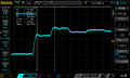
Reflection from an open circuit cable
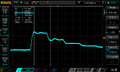
Reflection from same cable with a shorted output
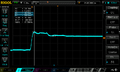
Much reduced reflection by terminating the end of the cable with a 47Ω resistor.

Looking at the signal on the far end of the cable. (note you can see the effect of the extra wire in the scope probe here!)


