Taking electricity outside
Taking electricity outside
This article is all about using electricity outside the home and discusses various ways power can be delivered to outbuildings like sheds and garages on a permanent basis. While in concept this does not sound as if it should be any more difficult than extending a power circuit from one room to another room in your house, there are a number of quite subtle details and safety issues that come into play as soon as you venture outside.
In particular:
- Outside Electrics
- Outside Sockets
- Outside Lighting
- Garage, Workshop, Shed & Greenhouse Power & Lighting
- Exterior cables, ducts, and armoured cables (SWA)
Note also that some of the work described here would be classed as a "notifiable work"
under Part P of the building regulations.
Decide what you want to do
This is probably the most important phase of the project, since if you don't think this bit through well enough you could end up spending lots of time and money on a solution that will not do what you need.
The primary questions to answer are:
- What do you plan to do with it?
- How much power is required?
What you plan to do in the outbuilding will dictate the power required. If all that is needed is a socket or two and some lighting, then the power requirements are fairly modest, a 13A supply would probably be more than adequate. To power a full workshop including equipment, lighting and heating however may require a far more substantial power supply. For the purposes of this article we are going to limit our focus to supplies that can reasonably be taken from a normal domestic household supply. If you need more power than that, then you may need to approach your electricity supplier about providing a dedicated supply to your outbuilding.
To estimate the total power requirement, think of the likely activities, and what equipment will be involved. What devices could you conceivable need to use at the same time. For example in a workshop you may need to use 1kW of dust extraction, a couple of kW of power tools, a kW of heating, and perhaps allow another 400W for lighting. If you add on some contingency for future expansion you get say: 5kW total, so perhaps a 20A or maybe even a 30A supply at 240V would be needed.
Design
Design is the process of working out how you are going to achieve each part of the installation, and using what type of equipment, what the required specification, is going to be for each part. We need to look at three aspects of the design:
- Head end: This is how you will take power from the house electrical system
- Submain: How you will wire the connection between the house and the outbuilding
- Outbuilding equipment: How you will select and install appropriate equipment for the outbuilding.
Each of these areas have to be addressed to ensure that the final result meets the required regulations and standards, does what you need, and is above all safe.
Note to complete this design exercise correctly you may need access to copies of BS7671 (the wiring regs) and the IEE On Site Guide (OSG) - 18th Edition Amendment 2 (affiliate links)
What you need to know
Distance
One of the primary things you need to know is how far you need to take power. This is not only the straight line distance between the house and the outbuilding, but also the distance from the consumer unit to the end of the electrical system in the outbuilding "as the cable runs", which may be significantly further.
The primary problem distance introduces is that of voltage drop. The longer the cable, the bigger its resistance, and the more voltage drop introduced for any given load.
Earthing
There are three commonly encountered earthing systems in use: TN-S, TN-C-S, and TT (see Earthing systems for more detail). It is important that you establish what type of earthing your property uses and this will influence the rest of your design.
Usage
The pattern of power usage you expect to make in the outbuilding will also influence your design. A design intended to provide power to a storage shed with one light, and a socket for running the mower and other garden tools from, probably does not need to worry about details like ensuring that the light does not fail should some other fault cause the power to "trip". Whereas in a workshop where you may be working at night with power tools or machinery this is a far more serious concern. A garage supply that will be used to run a chest freezer and the central heating boiler will need to make sure there is very little likelihood of a nuisance trip (see RCD) causing the contents of the freezer to defrost, and the heating to fail in mid winter when you are on holiday.
Head end design
From an existing circuit
Generally this form of supply should only be used for the simplest and smallest power feeds (i.e. no more than a 16A supply), since general purpose power circuits designed to supply sockets in the house, are not intended to provide power for heavy fixed equipment, or to supply substantial currents as a single "point load". You must also take into account the existing loading on the circuit before deciding to place additional demands on it. For example, many kitchen ring circuits often have existing loads that approach their full capacity.
This type of supply may be ideally suited to the provision of a single waterproof socket mounted on the outside wall of the building.
You will also need to take note of if the chosen supply circuit already has RCD protection. If it does not, then this must be provided for any socket outlets (with a trip threshold of no more than 30mA to offer adequate basic protection).
If it already has RCD protection, then this may make it difficult to meet your usage requirements since it might then be difficult to provide a lighting system in your outbuilding that is not vulnerable to interruption in the even of another fault that trips the RCD at the head end (i.e. you would lose "discrimination" - the fault would affect other circuits in addition to the one with the fault).
From a spare way in the CU
This is the more practical solution for most installations. It will allow you to take more power and in a way that will not affect other existing circuits. If you have a TN-S or TN-C-S system then you would ideally want to take power from a non RCD protected way on your consumer unit, this is to guard against the outside power feed increasing the likelihood of nuisance trips being caused on the household RCD, and also to prevent the RCD from making discrimination difficult for the outbuilding supply.
If your CU does not have a spare RCD unprotected way (or has a "Whole house RCD"), then consider using the independent supply method described below.
Using an independent supply
Where there is no available spare (or appropriate) way in the consumer unit, one can add a separate feed to a new consumer unit or switchfuse (this needs to be nothing more elaborate than a small DIN rail enclosure large enough to hold a switch and suitable protective device(s)).
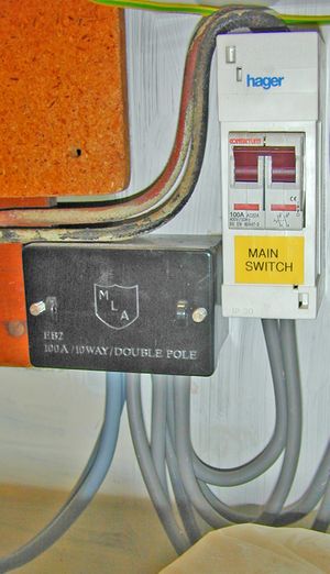
To feed this new CU, a big junction box called a "service connector block" (or "Henley block") is used to split the existing tails from the meter. The service connector block typically has room for five separate pairs of tails, so one pair of connections is used as the input and two pairs take power to the old and new consumer units. Probably the most elegant way to use this it to take the existing tails from the meter into a master switch first, and insert the Henley block after this. That way you retain the ability to kill the power to the whole installation with a single main switch.
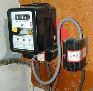
(This picture shows a Service Connector block (made by MLA rather than Henley in this case) being used to split the tails from the electricity meter. Note the original PBJ tails from the meter enter at the top of the switch, and new tails feed out to the connector block. From here two pairs of tails run to different consumer units)
The size of the tails used needs to match or exceed that of those used for the existing supply. This will typically be 16mm² for a 60A supply, or 25mm² for a 100A supply. If in doubt use the larger size since this will allow for a future upgrade to the supply without needing to replace all the tails. The new CU should have its earth terminal connected to the exiting main earth terminal using 16mm² earth single (6mm² on TT installations).
Choosing protective devices
It is necessary to provide protection for the submain since this will be vulnerable to damage, either en-route to the outbuilding, or in the outbuilding itself (especially where the building is readily combustible)
Provision of fault and overcurrent protection
Appropriate protection needs to be provided to protect the submain cable against fault and overcurrent. The most appropriate devices for this being either a MCB or a HRC cartridge fuse (fuse carriers are available in a MCB shaped enclosure for many brands of consumer unit). The fuse often has a slight advantage in that it will usually offer better discrimination with a downstream MCB. When using a MCB one may have to size it at least two ratings higher than the highest rating downstream device to ensure discrimination. This can be impractical in many designs.
The rating of the protective device will need to be selected so as to adequately protect the cable used. Note however that further calculations are needed to prove this devices is adequate (see submain design section)
Earth fault protection
For TN-S and TN-C-S installs one can usually rely on the fuse or MCB to also protect against faults to earth (e.g. the type of fault caused by a spade through the cable, or the shed going up in a puff of smoke!). With a TT install, additional protection will be required in the form of a RCD to protect against faults to earth, and maintain adequate shock protection from indirect contact faults. With the simplest outbuilding setups, it may be appropriate to use a 30 mA trip threshold device at the head end of the cable and forgo any further RCD protection in the outbuilding. Whilst this is a cheap solution, it is non optimal in many cases since it does not provide discrimination in the event of a fault to preserve lighting in the outbuilding, and it also means that one has to return to the head end to reset the RCD should it be tripped. A more practical solution is to use a 100 mA trip time delayed device at the head end, and a separate 30mA trip device in the outbuilding to provide the required direct contact shock protection.
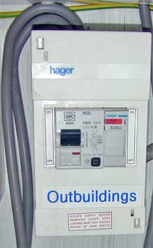
(This is a switchfuse on a TT head end, assembled from a small DIN enclosure. The incomer device is a 100mA trip RCD with time delay, and overcurrent protection is provided by a 30A HRC fuse in a fuse holder)
17th Edition Changes
The 17th Edition of the wiring regulations are now applicable and some new requirements in these may effect the design of outside electrical circuits. In particular: the new requirements for cable protection, and the implications of having a 17th edition style consumer unit.
Cable Protection Any cable buried less than 50mm deep in plaster or other building material, should now be protected either by earthed mechanical protection, or via a RCD with a trip current not exceeding 30mA. This means that any submain that your design required to be non RCD protected (for reasons of discrimination etc), will need to be routed carefully or provided with protection to meet this requirement. When using SWA cable this is obviously already meets the required protection level, however you may need to use metal conduit to protect T&E cable when that is used for the initial part of the cable run.
17th Edition Consumer Units These consumer units are often typified by being arranged as multiple way split load units. However unlike traditional split load units, cheap 17th edition CUs may have no spare ways that are not protected by 30mA trip RCDs. If the unit does not have an available non RCD protected way, then you may have to proceed with the alternate supply method of head end design if you need a non RCD protected submain.
Sub main design
This section deals with choosing an appropriate cable type, and checking the design parameters to make sure it is adequately protected.
Cable choice
The most commonly used cable types are flat T&E, HiTuff, or Steel Wire Armoured (SWA) cable. For more details including current ratings for the different cable types please see the main Cables article.
Cable types
| Cable type | Useage |
|---|---|
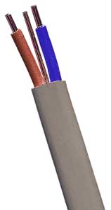
| Flat T&E | Twin and Earth cable can sometimes be suitable for use outside, although generally it is better protected inside conduit or trunking. Note however that it is not robust enough for direct burial. The PVC may also be attacked by the UV in sunlight which causes it to harden, and in turn this may make it more vulnerable to mechanical damage. (painting can help reduce this risk)
T&E would usually only be used outside for short runs, often clipped to the outside of the main building and out of reach in a location unlikely to be subject to mechanical forces or movement. Typical applications being connections to outside lights. T&E is however often used for the first part of a submain that makes the journey from the house CU to the point of exit from the building. One weakness of T&E that needs to be considered, is that its earth wire (CPC) is usually smaller in cross section than its main conductors. This will have a negative impact on the overall earth fault loop impedance of the submain. |
| HiTuf
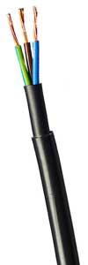
(Note double insulation layers) |
HiTuf is multicore flexible cable. While it is not suitable for direct burial it is robust enough for most other applications such as being clipped direct or suspended from a support wire. It will remain flexible under a wide temperature range, resists abrasion, and it is not affected by UV exposure. |
| SWA
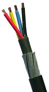
(Four core SWA. Note double insulation and armour wires) |
SWA is usually the cable of choice for many installations since it is available in a good range of core sizes, it is very robust, and can be buried directly into the ground with no need for further protection. Note that SWA is available with two alternative types of outer insulating material: PVC, and XLPE. The XLPE variety has a higher maximum operational temperature (90° C) compared to PVC (70° C), and hence a higher maximum current carrying capacity.
SWA is frequently not brought right into the building at the head end since it is relatively inflexible and difficult to work with. |
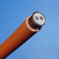
| MICC / Pyro | MICC (aka Pyro) cable is a robust metal screened and mineral powder insulated cable that is well suited to many outside wiring jobs except direct burial. Its small size can make for very neat and unobtrusive installations - especially when used on historic brickwork. Its also possible to "dress" the cable very neatly. Like SWA it must be terminated with the correct glands at each end. |
Voltage drop
Your design must ensure the maximum voltage drop allowed between source and point of use is not exceeded when at full load. Under the 16th edition wiring regs this was usually defined as 4% of the nominal supply voltage (about 9.2V at 230V AC). Under the 17th edition it has been relaxed to 5% (11.5V @ 230V) for most circuits, but tightened to 3% (6.9V @ 230V) for lighting circuits.
You also need to allow some of this voltage drop "budget" for the final circuits in the outbuilding.
SWA Cable
| Conductor CSA (mm²) | PVC (max 70° C)
Voltage drop mV/A/m |
XLPE (max 90° C)
Voltage drop mV/A/m |
|---|---|---|
| 1.5 | 29 | 31 |
| 2.5 | 18 | 19 |
| 4.0 | 11 | 12 |
| 6 | 7.3 | 7.9 |
| 10 | 4.4 | 4.7 |
| 16 | 2.8 | 2.9 |
Although these figures have been presented for SWA cable here, the values quoted are in general correct for other cable constructions. It is worth nothing however that these figures assume that the cable is operating at or near its maximum operating temperature (i.e. it close to its maximum current carrying appropriate for the way it is installed).
In designs where the maximum current load is significantly less than the capacity of the cable, then these figures will be somewhat pessimistic.
Cable Resistance
For these circumstances, it would be more appropriate to calculate voltage drops based on the following cable resistance data. Note this is a subset of the full table found in the On Site Guide (see table I1 in the 18th edition, and 9A in earlier versions). The OSG table includes larger copper conductor sizes and also aluminium conductors.
| Line Conductor
CSA (mm²) |
Protective
Conductor CSA (mm²) |
Resistance R1 + R2
per meter (mΩ/m) |
|---|---|---|
| 1 | - | 18.10 |
| 1 | 1 | 36.20 |
| 1.5 | - | 12.10 |
| 1.5 | 1 | 30.20 |
| 1.5 | 1.5 | 24.20 |
| 2.5 | - | 7.41 |
| 2.5 | 1 | 25.51 |
| 2.5 | 1.5 | 19.51 |
| 2.5 | 2.5 | 14.82 |
| 4 | - | 4.61 |
| 4 | 1.5 | 16.71 |
| 4 | 2.5 | 12.02 |
| 4 | 4 | 9.22 |
| 6 | - | 3.08 |
| 6 | 2.5 | 10.49 |
| 6 | 4 | 7.69 |
| 6 | 6 | 6.16 |
| 10 | - | 1.83 |
| 10 | 4 | 6.44 |
| 10 | 6 | 4.91 |
| 10 | 10 | 3.66 |
| 16 | - | 1.15 |
| 16 | 6 | 4.23 |
| 16 | 10 | 2.98 |
| 16 | 16 | 2.30 |
Notes on reading the table: The first entry each line conductor indicates the resistance in Ω/m for a single wire of that cross section. The remaining entries indicate the round trip resistance (R1 + R2) for a pair of wires. Typically either a line conductor and a (usually) smaller CSA protective conductor, or a Line and Neutral conductor (typically the same size).
To calculate the voltage drop based on these figures, multiply the resistance by the circuit current. E.g. for 20m of 2.5mm² carrying 16A, we can lookup the R1+R2 resistance per meter and get 15.82 mΩ/m. So the total resistance is 20 times that: 20 x 0.01582 = 0.3164Ω. So with 16A load that would drop 16 x 0.3164 = 5.06V
Calculation Examples (PVC SWA):

(Note examples based on the 4% drop allowed in the 16th edition)

1) 20m of 4mm², maximum load of 30A would drop 20 x 0.011 x 30 = 6.6V
2) 40m of 6mm², maximum load of 45A would drop 40 x 0.0073 x 45 = 13.14V
3) 10m of 1.5mm², maximum load of 16A would drop 10 x 0.029 x 16 = 4.64V

(1) and (3) are adequately specified with respect to voltage drop.
However (2) is out of  spec and a larger cable will need to be selected,
even though the current handling capacity of the 6mm² cable has not been exceeded.
Upgrading to 10mm², gives a result of 40 x 0.0044 x 45 = 7.92V which is acceptable.
It initially appears that this still only leaves just over 1V of remaining drop
available for the outbuilding wiring, however since we will not be operating the
larger cable anywhere near its maximum temperature, the situation is actually less
tight than the calculation suggests.
Disconnection time
In the event of a short circuit fault in the sub main, the circuit protective device is required to disconnect the supply within 5 seconds (or 1 second for TT head ends). Two short circuit faults are possible: phase to neutral, and phase to earth. In the case of a TN-S or TN-C-S installation at the head end, we calculate the disconnect time for a phase to earth fault since this usually represents the worst case and the phase to neutral disconnect time will usually be the same or faster. For TT installations the phase earth disconnect time is dependant on the RCD, and hence does not need to be checked by calculation.
TN-S & TN-C-S Earthing at the head end
To establish the disconnect time we first need to calculate the earth fault loop impedance. This will comprise the sum of the impedance of the suppliers earth (Ze), plus the round trip impedance of the selected cable from the head to the location of the fault. Where a submain has more than one cable type (i.e. a T&E feed through the house, with a SWA section outside) the total impedance for each section should be added. In the absence of a measured value of the suppliers earth impedance one should take this as 0.8 ohms for TN-S and 0.35 ohms for TN-C-S systems (note that these values are pessimistically high, and may cause difficulties when designing sub mains for higher current supplies. In these circumstances is it advisable to actually measure the value and use the measured value in place of these worst case figures).
Example: A submain with 5m of 6mm² T&E and then 15M of three core 6mm² SWA on a TN-S supply
using the third core as a CPC, protected by a 40A type B MCB.

We will assume that the fault is at the far end of the SWA section, since this will
represent worst case.

From our Wire Resistance Table, we know the 5m of 6mm² cable will
represent 10.49 mOhm/m or 0.052 ohms in total.

From table 9A of the OSG, we know the 15m of SWA will give 6.16 mOhm/m or 0.092 ohms

So total earth fault loop impedance Z(s) = 0.8 + 0.052 + 0.092 = 0.944

This gives a maximum prospective fault current of 230 / 0.944 = 244 A

Reference to figure 3.4 in BS7671, shows the 0.1 second disconnect time for a
40A type B MCB will be achieved with a fault current of 200A (i.e. less than calculated)

Therefore we can conclude that the design meets the disconnect time requirements.
If the required disconnect time is not met then the cable CSA will need to be increased or the protective device rating reduced.
CPC sizing
The final stage is to check that the CPC of the submain will withstand the duration of a fault condition for long enough to allow the protective device to operate. We know the section of T&E cable will have the poorest performance in this case, so we can check to see if its 2.5mm² CPC is ok.
Continuing with the above example:

s = sqrt( I² x t ) / k

Where k is 115 for PVC insulated cable (table 54C of BS7671) - See table here for other cable types

s = sqrt( 244² x 0.1 ) / 115 = 0.67mm²

Which is smaller than the 2.5mm² of the 6mm² T&E cable

so we can conclude the cable's CPC is of adequate size.
Using SWA armour as a CPC
In most cases where an earth is to be exported to an outbuilding via a SWA cable, the ideal way to do this is usually via the use of the cable armour wires and the correct termination glands. Hence it is useful to know the total cross sectional area of the armour wires and also the armour resistance of the cable to be able to perform the calculations described above.
Note that for any SWA likely to be encountered in a domestic setting, the CSA of the armour will exceed that of the conductors.
For 90° C XLPE clad SWA - Steel Armour (figures from BS5467:1997)
| Phase Conductor CSA (mm²) / Resistance (mOhms/m) | CSA of armour (mm²) / Resistance (mOhms/m)
2 Core SWA |
CSA of armour (mm²) / Resistance (mOhms/m)
3 Core SWA |
CSA of armour (mm²) / Resistance (mOhms/m)
4 Core SWA |
CSA of armour (mm²) / Resistance (mOhms/m)
5 Core SWA |
|---|---|---|---|---|
| 1.5 / 12.1 | 15 / 10.2 | 16 / 9.5 | 17 / 8.8 | 19 / 8.2 |
| 2.5 / 7.41 | 17 / 8.8 | 19 / 8.2 | 20 / 7.7 | 22 / 6.8 |
| 4 / 4.61 | 19 / 7.9 | 20 / 7.5 | 22 / 6.8 | 25 / 6.2 |
| 6 / 3.08 | 22 / 7.0 | 23 / 6.7 | 36 / 4.3 | 40 / 3.9 |
| 10 / 1.83 | 26 / 6.0 | 39 / 4.0 | 42 / 3.7 | 46 / 3.4 |
| 16 / 1.15 | 42 / 3.7 | 45 / 3.5 | 50 / 3.1 | 72 / 2.2 |
| 25 / 0.727 | 42 / 3.7 | 62 / 2.5 | 70 / 2.3 | 88 / 1.8 |
Note that for ease of use when checking that the armour is of adequate size for a proposed
circuit design, one needs to use a "copper equivalent" of the armour CSA in the calculation.
To do this divide the quoted CSA figure by 2.255.

So for example: a 2 core 2.5mm² cable copper equivalent armour area of 17 / 2.255 or 7.54mm²

Note however that the calculated copper equivalent area is only for use in the adiabatic equation
described above. If you need to compute the actual armour resistance then use the resistance figures
quoted instead.
Outbuilding equipment design
The final design stage to to select appropriate equipment for location in the outbuilding.
Know your environment
To make a sensible selection we need knowledge of the local environment. The phrase "outbuilding" can encompass anything from a damp draughty shed, to something as civilised as your front room.
Hence establish:
- How damp is the interior likely to get?
- Is it easy to make a good contact with earth? (e.g. A wood floor in a workshop that has no extraneous metal parts in contact with earth and no other services like water pipes entering the building will offer a good isolation from earth, whereas a greenhouse sat on damp ground would offer none).
Exporting an earth
The first major design decision to make is how the earth will be provided to the building. The options are to either export the house earth, or to use a local earth spike and create a local TT installation at the outbuilding. (for information on installing TT earthing, please see this article)
| Earth Type | Limitations | Advantages | Disadvatages |
|---|---|---|---|
| Exported |
|
|
|
| Local |
|
|
|
When exporting an earth, the earth continuity must be maintained all the way through the installation from head end to submain, and into the final outbuilding circuits. With a locally (TT) earthed outbuilding this is not the case. Here the earth at the house end will typically be connected to the submain for the purposes of giving it fault protection for the run to the outbuilding, however it would be isolated at the destination. Here the local earth rod connection would be used for the outbuilding. One way to achieve this isolation when terminating at a CU is to use an insulated CU (i.e. plastic), and not fitting or connecting an earthing ring to the cable gland. (note that since the 3rd amendment of BS7671 17th edition introduced a new requirement for CUs to be made from a non combustible material, there is a much smaller range of plastic enclosures still available than at one time).
Exporting an Equipotential Zone
Great care must be taken when exporting an earth from a TN-C-S (PME) head end. One of the potential faults with these installations that needs to be given consideration is what happens if the suppliers neutral were ever disconnected but the live left unaffected. This would leave the neutral and the earth floating. Given it would be connected to the live side of the supply via all your appliances, and there would be no current flowing, the potential of the neutral and earth (and by implication the metal cases of all your appliances) would tend to rise to 240V. This obviously raises a serious shock risk. There are a number of things than can be done to mitigate the effects of the problem. One of these is good equipotential bonding - making sure that an equipotential zone exists in the house that electrically commons together anything that might acquire a different electrical potential from the electrical earth/neutral. This has two effects - the fortuitous earthing of things like water and gas supplies will tend to lower the touch voltage experienced anyway, and more importantly, if you are unable to make contact with conductive parts that are at significantly different voltages, its hard to get a shock in the first place - even if the things you are touching are all at 240V.
Hence if exporting the PME earth to the outbuilding, you need to ensure the equipotential zone is extended there as well if there is any possibility of contacting anything in the building that could be connected to an independent local earth.
Also note that if one is exporting the equipotential zone, that probably means the CPC of the submain is also being used as a main bonding conductor, and so it will will have to meet the minimum CSA size requirements for a main equipotential bonding conductor. Since this is often 10mm² of copper (or an appropriate CSA of another metal offering equal conductance), it will preclude the sole use of the armour wires as a combined CPC / Bonding Conductor, since the armour resistance is typically too large (this is generally true for all SWA cables less than 70mm²). In these cases a separate bonding conductor operating in parallel with the armour can be used.
When something goes wrong
You need to consider how you are going to contain the impact of a protective device opening and cutting off power to a circuit, or the entire outbuilding.
With the simplest installations, RCD protection could be provided at the head end. This keeps the outbuilding install simple, but means in the event of a RCD trip all power is lost to the building. For a simple storage shed this may be acceptable.
With a workshop, more careful design is required to ensure that nothing short of physical damage to the submain will result in power being disconnected at the head end. Use of a split load CU, or emergency lighting could then ensure lighting remains on in the event of a power circuit trip.
When protecting power feeds to freezers or boilers in outbuildings, it may be appropriate to feed them from a dedicated circuit and treat them as fixed equipment. Thus the can be placed on the non RCD (or higher trip threshold) side of the outbuilding CU.
IT Equipment would be best protected with an uninterruptible power supply unit, and possibly a trip alarm.
Installation
Installing the head end
From an existing circuit
Turn off power to the circuit. An appropriate fused connection unit can then be inserted into the circuit to take power. In the case of non RCD protected circuits a RCD protected spur could be used (ideal for feeding external lighting circuits mounted on the outside of the house wall). For supplies to sockets on the outside wall of the house, it may be more appropriate to use a RCD protected socket. That way you would not have to come inside in your muddy boots to reset the trip should it activate!
The cable from the spur can exit at a convenient point including from directly behind the FCU if a hole is drilled in a suitable place. Remember to drill any hole at a slight downward angle to prevent moisture ingress. Also construct a "drip loop" (i.e. ensuring the cable runs down first for a short distance at the exit point so that water can not run along the cable and be directed into the hole).
From a spare way in the CU
Turn off power at the CU. Remove a blanking plate and fit the protective device to the selected spare way. Remember when fitting a cable to a split load CU to connect the neutral conductor to the appropriate neutral bus bar.
Using an independent supply
Disconnect power to the CU. If you have a main switch available that can interrupt power to the CU then use this. Typically however this will not be fitted. In these circumstances it will be necessary to remove the suppliers main fuse that feeds the electricity meter. If the fuse has not been pulled previously then it will probably be sealed with a paper tape and/or wire seal. These will need to be broken or cut first.
It is vital that all loads are switched off before removing this fuse.
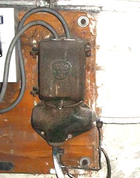
(The main fuse is shown on the right here, on this one the seals have already been removed)
Note that the main fuse is the property of the electricity supplier, and it is
technically illegal for you to touch it. The "correct" way to arrange for
disconnection of a supply is to contact your power distributor and book a visit
from one of their contractors.
Most electricians will routinely pull main fuses without permission, and most suppliers will turn a blind eye to the practice (many would probably admit informally that they would rather the main fuse was pulled than someone attempted to work live).
| WARNING
Most main fuses / cutouts that you will encounter have an enclosure made from plastic or a Bakelite like thermosetting material. If however you have metal-clad main fuse / cutout (typically pre 1940s), then it is strongly advised that you do not touch this yourself and instead get your electricity supply company to arrange for a temporary disconnection. This is because these fuses may now be very fragile, and pose a serious short circuit and/or explosion risk if they are disturbed since these can pull the main incoming live straight onto the earthed metal enclosure due to age and fatigue. |
With some designs of main fuse it can be advisable to cover the live end of the enclosure with insulating tape as a temporary safety precaution, since otherwise a live contact (now without fault current protection!) is relatively easily accessible to a misplaced finger or tool.
The existing meter tails can now be disconnected from the consumer unit and connected to the service connector block (preferably via a new "main switch" enclosure). Try to avoid breaking the seals on the meter end of the tails, by working only with the CU end. New tails can now be wired from the service connection block to the original CU and to the new CU. Remember to also use an appropriately sized earth single to connect the earth terminal in the new CU to the main earth terminal. Make sure that all terminals are well screwed down. Visually inspect your work, and then confirm all connections paths are as expected using a low ohms range on a multimeter. Refit the covers. Refit the main fuse (again ensuring there is no load present on any circuit).
Installing the sub main
In many cases the sub main will exit the building at the head end and vanish into the outbuilding at the destination. However with some of the heavier less flexible cables such as SWA this is not always easy. Here is is often easier to terminate the SWA at the outside wall of a building at a waterproof adaptable box using the correct waterproof gland kits, and join to a alternative cable such as T&E that will run the remainder of the distance inside the building. In some cases one may choose to just run the inner part of a SWA cable through the building to the head end (i.e. stripping the outer insulation and the armour) however an earth connection will need to be made to the armour when you do this.
Cable routing
Cables can be routed in anyway you like, so long as they are adequately protected, and supported along the route. Note that permanent cabling should not be run on a temporary structure such as a wooden fence.
Surface Clipped
Cables can be fixed to any sensible permanent surface where they are unlikely to be damaged. This can be using ordinary cable clips or cleats. They can also be run along cable trays and other cable support systems. (One handy tip when using the large "P" clips with SWA cable on hard surfaces, is to drill a 5mm hole first, and tap in a yellow wall plug. Then nail the clip into the plug with the supplied pin).
Overhead
Cables can only be run a short distance in open space when unsupported. In most cases it will be necessary to erect a catenary wire first to support the cable. The cable is then tied to the wire at regular intervals to support it. This will prevent the cable stretching and the insulation being damaged or abraded at the point of support. The wire height shall be chosen to ensure that it does not pose any hazard to passing pedestrians or vehicles.
A cable supported like this must also be UV resistant, and of a flexible construction such as Hituf (T&E cable is not suitable)
Direct burial
Cables such as SWA are suitable for direct burial. There are no hard rules as to how deep a cable should be buried, but the depth should be appropriate for the situation. Under a path this may be as little as 400mm, but could rise to 700mm or more under part of a garden that may be "dug over". The cable trench should be cleared of any sharp stones that may damage the cable insulation. If this is not easy to achieve, then a lining of sharp sand or pea shingle can be laid in the trench first. After backfilling the trench the first 150mm, a PVC "Cable Below" tape should be laid before the rest of the trench is backfilled. That way anyone digging too close to the cable will hit the warning tape before hitting the cable.
Ducted
In some circumstances ducting may have been provided to take cables to the outbuilding. Note that it is not permissible to run power cables in the same duct as low voltage data and signal cables, unless it is a specially designed segregated duct designed for the purpose. Also note that ducting will probably require the derating of of the submain cables maximum current carrying capacity.
To feed a cable through a duct it is generally preferable to pull it through using a draw wire, rope or string (fishing line works well for this since it is slippery and strong). To ease the process having an assistant push the cable from the other end can help. In extreme cases lubricating the cable can also help (there are dedicated cable lubricants available for this purpose, that will not damage the cable insulation).
Pulling the cable through may be easy, but that does leave the question of how to get the draw wire through in the first place! There are a number of options:
- The wire can be placed into the duct as it is assembled and buried
- For smaller ducts, a small section of rag tied to the end of the draw wire will enable it to be sucked through using a vacuum cleaner at the far end.
- Blowing it through with a supply of compressed air can also work - although you need to make a loose seal at the end you are blowing so as to keep most of the air in while letting the draw wire move freely.
- Using a set of push rods (or even drain rods on big ducts)
Installing the outbuilding equipment
A fundamental requirement for all electrical equipment selected for installation in your outbuilding is that it must be appropriate for the location and the expected use. This does not mean it has to be colour co-ordinated, but it does need to be moisture resistant if the building can not be assured of remaining completely dry. Some thought should also be given to impact resistance. In a workshop, that is to use surface mounted sockets, one of the "metal clad" range of sockets and accessories might be suitable since it offers better impact resistance. Adequate protection should be given to light fittings as well. Experience in my own workshop would suggest that the plastic diffusers on the fluorescent strip lights have saved countless tubes from impact with over long planks etc.
Basic installs
The simplest systems to install are ones where there is just a feed to a small number of sockets and perhaps a light fitting. The overcurrent, fault, and RCD protection will have probably been taken care of at the head end of the supply. If the supply is not RCD protected then sockets with integral RCD protection could be used, or a RCD spur be installed to supply a small group of sockets.
Typically the incoming cable can be terminated in an adaptable box, and the wiring can continue directly to the sockets via flat T&E (radial circuit). In damp environments careful attention should be paid to fitting cable glands, grommets, and seals where needed (this also keeps out a good number of the small bugs that might otherwise seek to find a nice dry place to sleep!)
If the current carrying capacity of the interior wiring is equal to or greater than that of the overcurrent and fault protection provided at the feed cable head end, there will be no need for further protection at the transition.
To provide a supply to a lighting circuit a simple FCU protected with a 5A fuse can be used (or a switched fused FCU if you want to save the cost of a dedicated light switch!). It is better not to rely on switches integrated into the light fittings in most cases, since they may not respond well when groped with wet hands in the dark.
Mid range
Mid range installations will usually use a small "garage" CU. Small CU installs like this are useful for when it is necessary to provide local protection to various circuits rather than rely on blanket protection provided by the submain head end.
While these are a neat and simple solution, a failing of most of them is that they have a RCD which protects all circuits. While this will be a requirement for local TT installs (although a single 30mA trip RCD may not be the optimal solution), it may lead to unacceptable loss of lighting or other critical circuits. In these cases it may be necessary to look at full CU installs (see below), or to provide emergency lighting. Note for this reason this type of CU is not well suited to supply Freezer or boiler feeds in a garage.
The incoming submain cable can often be terminated directly into the CU. Alternatively an adaptable box can be used to change cable types to flat T&E if this makes the cable handling and routing (remember to allow for this in your design calculations).
Full consumer unit installations
In this catagory we will include any of a number of "roll your own" solutions that assemble CUs and protective devices from a range of parts, rather than using a packaged solution in a box.
A neat and simple solution for many installs of this type is the use of a simple non split load CU with a RCBO for the socket circuit. For TT installs the incomer switch can be replaced with a 100mA time delayed RCD, or alternatively a completely separate CU could be provided for non socket circuits with its incomer replaced by a conventional 100mA trip RCD.
For larger outbuilding installs with more than a couple of circuits, a domestic style split load unit may be more cost effective. This is an extension of the above.
Testing
Provision of a supply to an outbuilding should be tested as any new circuit should be. Special attention should be paid to insulation resistance checks, and also in the case of system with exported PME earths (TN-C-S head ends), the integrity of the local equipotential zone should be tested.
External Links
- Electrical Installations Outdoors article in IET "Wiring Matters"
See Also
Keywords
Outside electrics, outdoor electrics, garden electrics, garage electrics, garden power, shed power, outbuilding power, garden electricity, shed electricity, garage electricity, outside wiring, outdoor wiring, garden wiring, exterior power, outdoor socket, outdoor lights
