DIY Loft conversion
This is the story of a part DIY Loft Conversion project that I carried out in the early 2000s on a 1950's semi detached house. Previously hosted on the main Internode Ltd web site, it has been moved here, lightly updated, and a few new photos and other extra bits included along the way.
A point worth noting is that some of the regulations relating to loft conversions have changed in the time since the work described here was done. So while what we did was correct at the time, some of the things we did would not meet the regulations as they stand now.
So please refer to the current building regulation approved documents, and take proper advice if needed.
Also note that any prices shown here are 2004 prices, so remember to adjust for inflation!
Introduction
The usual story: too much stuff, too many people, and not enough house! Not saying the place is small, but you do get the feeling you need to step outside just to change your mind. So In late 2003 a plan was formed, at the start of summer in 2004 we would rip the roof off, stick in another layer, and put the roof on again. How difficult could it be?
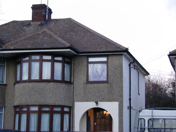
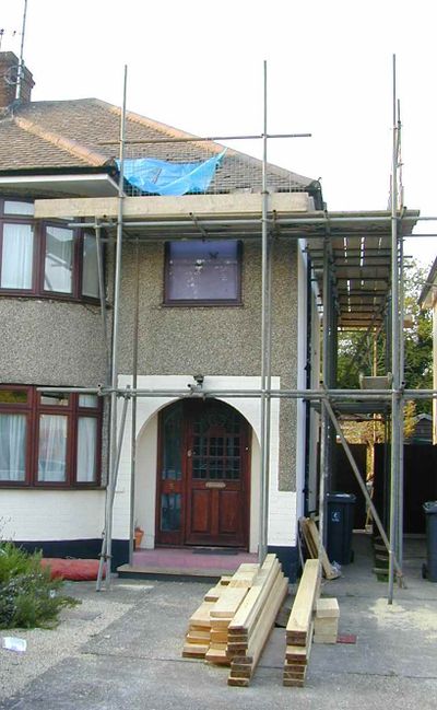
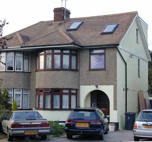
The obligatory "before" picture:-
Being brave I thought I might tackle this project myself ;-) However not being that brave I thought it might be a good idea to seek help from someone who has done this before. Not only that we need the space sooner than Christmas 2006 (which is how long it might take if I did it all myself!) Hence my mate Trevor, a joiner and builder by trade.
The Research Phase
For a job like this planning is essential! It does not take long to realize there is a lot to learn either. A good starting place is the hugely talented and helpful collection of regulars over at the uk.d-i-y usenet group. You can also find some other articles I have written here in the DIY Wiki inspired by some of the work done here.
Planning and Building Regulations
Many loft conversions do not actually require planning permission (PP), and this one is no exception. However, they do require a "Full plans submission" to the local district council. PP would typically be required if you wanted to make changes to the roof line the faces the road (by addition of a front dormer for example). Oddly converting a hipped roof to a gable end wall does not seem to count as a change in this sense!
Hence the first requirement was getting some plans drawn. Finding an architect with time available was also tricky.
If I were doing this again (now having seen a set of plans and the associated structural calculations) I might be tempted to do them myself. The plans are pretty straight forward diagrams of the property from each elevation, and the structural calcs are produced straight out of superbeam. The only tricky bit would be coming up with the source data to use for beam loadings. Having said that, most of the "industry standard" figures can be had from a book like this (affiliate link).
Having got a suitable set of plans, these were submitted to the council (along with a cheque for £88 to pay them to look at them!). The building control officer (BCO) will usually reply to these and suggest any alterations to bring the plans in line with current regulations and "best practice". If there are any changes required these are then made to the plans and they are resubmitted. Usually at this stage approval will be granted, or, if there are problems with the resubmitted plans you can go through the adapt -> submit -> comment cycle for a few more iterations.
In our case the BCO replied (in almost illegible hand writing - how quaint), with a few minor comments which could be easily added to the plans. The resubmission was approved and we were under starters orders. You can now pay a further £264 to building control to have them come and OK each stage of the build.
[Editors note, check your local authority web site for their building control department - they probably publish a set of prices for full building notice and full plans submissions]
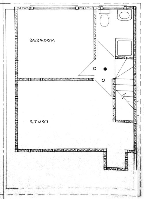
Anyway the plan is to add three new rooms:
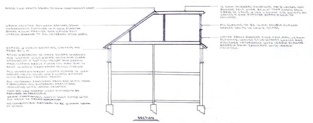
And they will fit into the new envelope like this:
Since the front roof will still retain its slope, the wall to the front is a dwarf wall that will have doors providing access to the remaining storage space at the front of the loft.
(note that both the above piccies don't show the big bay window that runs the full height of the house and sticks out of the front, or its associated bonnet roof).
Preparation
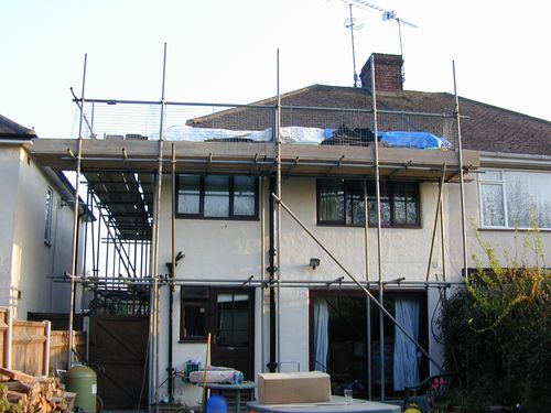
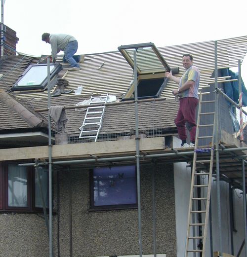
Next job was gaining access to the loft. First we need to be able to reach it, so we got scaffolding installed around three sides of the building
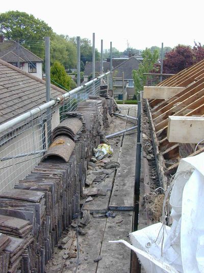
We also de-tiled and de-battened a section of roof at the front so that we could get stuff in and out of the loft without needing to move it through the house. This made it much easier to get long timbers in and out as well as keeping most of the mess outside!
Boiler
Another "to do first" job was setting about the heating system.
The house had a traditional vented "heat only" boiler wall mounted in the kitchen with a feed and expansion tank in the loft. The loft also housed the main cold water cistern (raised into the apex of the roof on a platform) and then a traditional hot water cylinder on the loft floor below it.
There was also a fair amount of pipework and the CH pump. Needless to say that was all in the way.
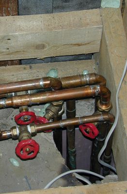
So I ripped all of that out, and installed a 35kW modern condensing combi boiler. This allowed the RADs to be converted to a sealed system doing away with the need for a feed and expansion tank. It also generated all of the hot water for the house without the need for a cylinder. So that got shot of the main cistern, cylinder, pump and much of the pipework.
The new pipework was brought up to enter the loft through the floor where the new shower is shown on the plan above.
Combis are usually a bit of a compromise since they can't usually match the hot water flow rate of a storage system, but in this case there was not much alternative. Also the existing vented system was poorly implemented and so did not work that well in the first place. Going for a high power combi meant good mains pressure showers, and moderate bath filling speed.
The new floor
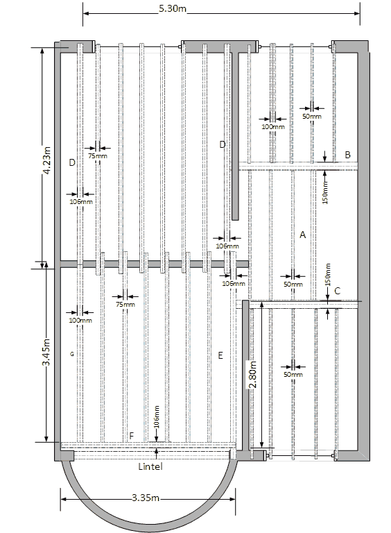
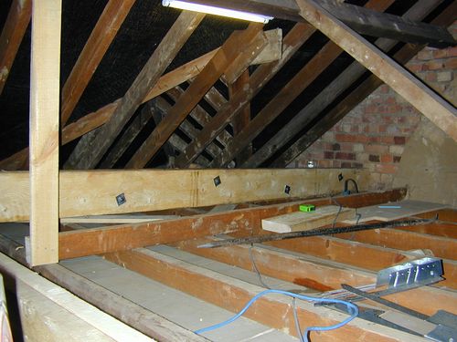
The first major job is strengthening the floor. Although the existing loft floor is comprised of 4x2" timber (which would be fairly substantial timbers by modern loft standards), this is nowhere near strong enough for a new floor. Hence the need to play a game of inserting lots of 8" deep beams into a space while dodging all the existing beams.
Some of the longer joists also need to carry point loads from other joists or "stringers" that meet them. As a result, a simple timber beam is not always going to cope without deflecting too far (to meet limits imposed by building regulations), or being dangerously overloaded.
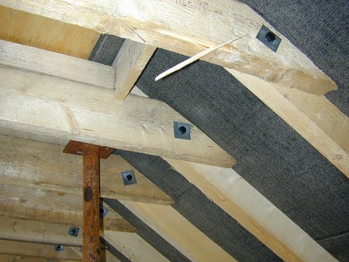
In these situations "Flitch" beams are used. These are made with a steel plate sandwiched between two timber beams, and the whole lot bolted together every 600mm.
A few words on structural design
All of this needs to be properly designed and proven by detailed calculations before construction.
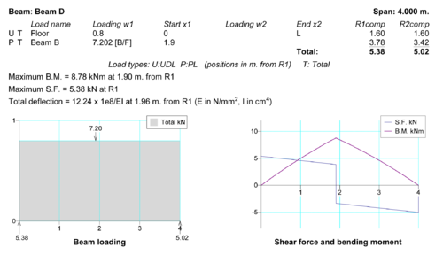
The plans called for a 6mm thick plate - the steel supplier gave us a free upgrade to 8mm (fine except it makes the things a bit more difficult to manhandle). They also take care of drilling the holes and painting them with a (red) passivating paint.
Most of the windows in the house are of a span of under 2m with a nice concrete lintel over them. The main bay window at the front however is much wider. Rather than pull apart the rooms below to establish the construction of the lintel over these windows we decided to use another flitch beam as a stringer to carry the front floor joists. This first photo shows it being manoeuvred into position. It is deliberately placed over the existing loft floor joists since these are being used in a cantilever to hold up the front bonnet roof over the bay. The front floor beams will be hung from this flitch beam on long joist hangers.
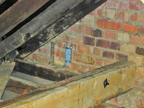
The beam is supported at one end of the longitudinal flitch beam (Beam E), and at the other in a heavy shoe bolted to the party wall with sleeve anchors.
Note the original loft floor had "tie" beams that ran across the width of the loft to keep all the other floor joists ridged and add extra support for the weight of the ceilings below. Each time we crossed one of these, we needed to batten the beam to the purlins above before we cut it. This is to ensure that we do not introduce any more sag into the ceilings below. Once the joist was in place "noggins" could be added between the new joists to hold the old floor joists instead.
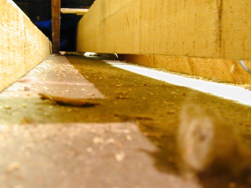
The new floor beams sit on a 1" thick wood plate laid on the top of the supporting walls. In this way the new beams sit a little above the existing ceiling level and do not come into contact with it. This way there is no danger of them causing cracks or damage to the ceilings below when they are loaded.
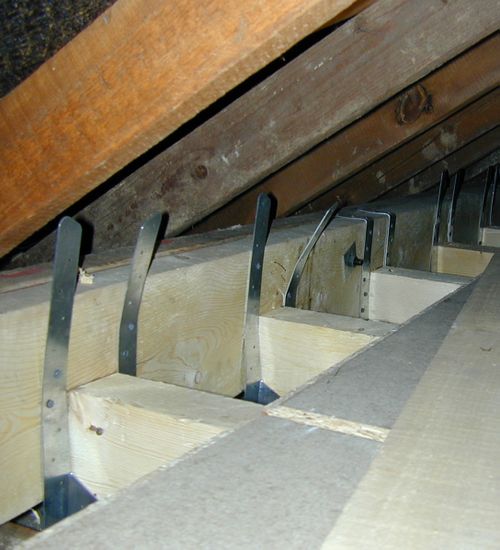
It is interesting to see just how far the ceilings have sagged over the years just from their own weight (plus that of any stuff stored on them). The 1" gap at the end can be as much as 4" in the centre of the span. Not that this is actually noticeable from the rooms below.
Getting close to done.
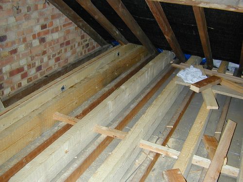
The new floor joists are now in place. This picture also shows the noggins that replace the original tie beam that steadied and supported the original ceiling joists. These are nailed between the new joists and also onto the old ceiling joists. The only downside of this is that you now couple the new floor to the old ceiling slightly which will increase noise transfer a little. (in reality the effect is small and noise transfer is far less between 2nd and 1st floors than it is between 1st and ground).
In total we only had to remove one of the existing floor joists close to the party wall so we could get the main rear flitch beam into its proper place. This was a delicate operation of chain sawing the original beam into short sections (without going through the plasterboard ceiling that is nailed to the underside of it), and then pulling up each section so that it rips the plaster board nails through the back of the board, hopefully leaving the finish to the ceiling below undamaged. Remarkably we only damaged one small section of ceiling when we hit a nail with the chain saw, and a 50p sized bit of artex and skim decided to jump off the ceiling!
Floor Complete
Completion of the floor is one of the major structural milestones of the build, so we invited the BCO to come and check before we carried on.
Superstructure
Once the floor was done and approved, we needed to set about the roof, and convert the hipped roof into a new gable end. Alas this is not quite as simple as just pushing it up straight!
De-tiling
The first rather dull job is to remove and stack all the tiles from that bit of the roof.
Removing tiles is actually simple enough with two people. One sits on the top of the roof, picks up each tile in turn, flips it over and lets it slide down the roof. Someone at the eves grabs them and stacks them.
Removing the Hipped End
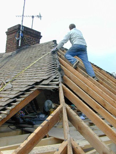
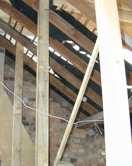
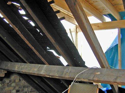
Once all the tiles were off the hipped end, we stripped off strip off all the tile battens, then the old sarking. While we were at, it we also de-nailed all the rafters (we will reuse the timber for the studwork in the gable wall).
Once the load is off that side of the roof, we stuck an Acro under the ridge where it met the hipped roof to stop that moving (the front and rear tile loads still balance each other at this point).
Next we took out the purlin that supported the hipped roof rafters at mid span, and finally cut away the roof timbers.
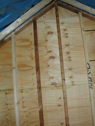
Now we could build the studwork for the gable end wall, and clad it in 3/4" ply. This is actually a reasonably quick process. We start by making a copy of one of the existing front rafters to use as a pattern, then all of the required new rafters are produced quickly just by copying the pattern. The first two rafters at the gable end are inserted - nailed to the supporting walls at their "bird's mouth" joint, initially just resting on each other at the apex of the roof line.
Next the extension to the ridge beam can be inserted. Since access to the existing ridge is restricted by other rafters and the original hip beams, this is just tack nailed until a better joint can be made later.
The wall in then built up from studs at 400mm centres with another beam inserted at the top, level with the underside of the edge rafters. Ultimately this will be the beam to which the outriggers can be fixed that will support the fascia/barge boards to the edge of the roof.
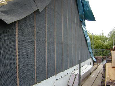
The outside of the wall is then felted with "under tile felt" (i.e. the hessian reinforced stuff). This is just tacked into place with a few galvanised nails bent over at the ends.
Next 6mm thick battens (made by ripping strips of the side of a sheet of ply) are nailed down over the felt in line with each stud.
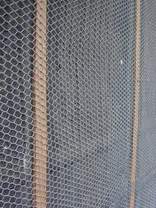
Finally EXPAMET "expanded metal lath" mesh is then carefully stapled over the whole surface ready for rendering.
Finishing the Front
Having got the gable wall in place the next priority is to get the front roof section completed since it is not dependant on any other parts of the build. Once this is done it can be felted and have the tile battens nailed on after which it should be reasonably watertight even without the tiles.
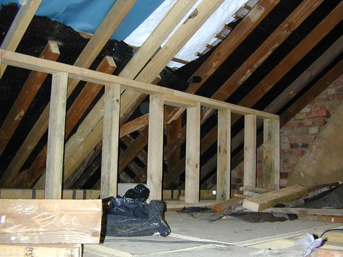
One of the key requirements for the front roof section is the construction of the dwarf wall under it. This serves several purposes. Firstly it will support the weight of the roof (taking the place of the main roof purlin that we needed to remove). It will also provide a suitable "end" to the room (rather than have it tail off to a point in the eves), and finally it will have some access doors inserted so as to reach the remaining loft space that is now behind this wall.
First Roof Window in
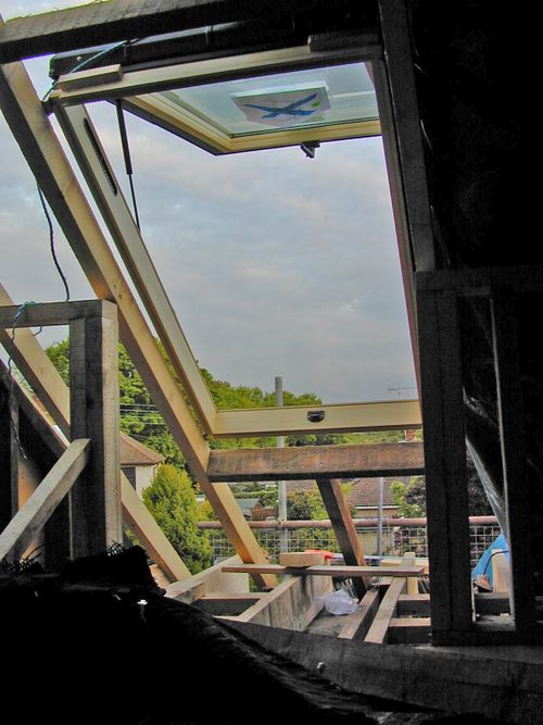
[Editor's note: Means of escape windows onto pitched roofs ceased to be a building regs requirement after we completed this build - ultimately it was decided it was more dangerous to try and escape from a burning building at night onto a sloping roof two storeys up, than it was to instead focus on protecting the means of escape through the lower storeys]
The second window will be inserted much higher than this toward the other end of the room, so as to spread the light about a bit. We have elected to use two windows of the same size and type even though there is no requirement for a second means of escape window. The top opening design also means that us taller folks will be able to stand upright in the second window when it is open and look out!
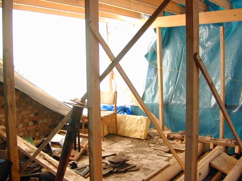
For the first time in a week the weather has been good enough to take the covers right off the front of the roof! This makes progress much quicker. We are also now on the reconstruction phase of the front roof. The whole lot has been felted and battened so should at last be water proof (so I can play fewer games of "find the leak and stick a bucket under it!")
However we will not do all of the tiling on the upper roof section until the rear dormer is in place, and we can properly support the ridge beam without needing the balancing force from the rear roof section.
The Rear Dormer
Having got the front mostly done (except for a few tiles towards the ridge and the eves) we can now turn our attention to the rear dormer. This is the last major bit of structural work that we need to do.
The design here is a little unusual. Traditionally when you add a large rear dormer you would need to insert a large (usually steel) beam under the ridge of the roof to support the weight of the front tiled section (since you will be taking away the matching rear roof section that has until now balanced the front section and kept it in place. However, this conversion has a partition wall not far from the centre of the house, which can instead be made load bearing. Since it is not directly under the ridge it instead holds one end of the roof joists for the dormer - these in turn run over the partition wall and meet the ridge where they can act in cantilever to support it.
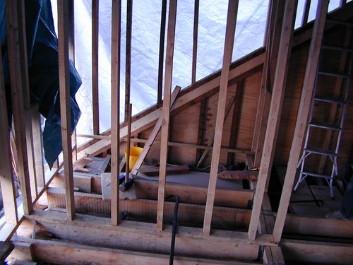
To construct the dormer we need to erect some of the partition wall studwork, and also the rear "goalposts" which carry the other end of the roof joists:
The new flat roof joists can now be joined to the rafters under the ridge beam:
Finally we can introduce the remaining rear roof timbers to the chainsaw, and "let out" some space!
Internal Walls
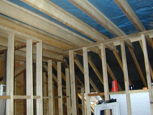
Now that the main "envelope" of the structure is in place we can start filling in the walls. This is a two stage process. The first is the cladding of the exterior of the dormer (the exterior walls being finished in the same way as the gable end with a felt and EML layer on top prior to rendering). The second is the building of the internal studwork that will later form the dividing walls.
Fire Break
One of the usual observations about running any large project is true of this one. That being, that doing 90% of the work takes 90% of the time. Doing the remaining 10% of the work takes the other 90% of the time!
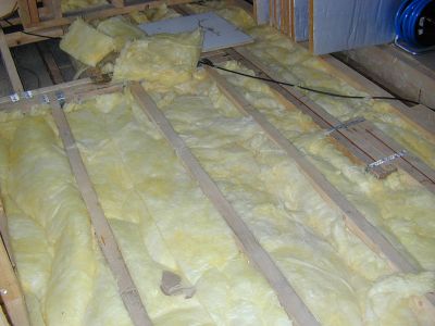
Building the entire supporting floor structure only took six days, some other "little" jobs seem to take as long or longer! One such job is a result of a comment made on the plans by the BCO - that if the plasterboard thickness to the first floor ceiling was not 12.5mm, then one should use rockwool suspended on chicken wire to improve the fire resistance of the new floor. By the time you have got a roll of chicken wire and cut it in half, then proceeded to unwind the irritatingly twangy 100M of stuff and stick it between all the joists, then staple it in place, and finally overlay it with that vile creation rockwool (or Isowool as we actually used) you have spent an awful lot of itchy scratchy days doing it!.
(On the bright side it will also reduce noise transmission between storeys)
Although not a "fun" job, it does add some extra escape time in the event of a fire (and that becomes more important when buildings go over two storeys tall).
Superstructure Done
So that is the bulk of the superstructure work now done. Now we need to focus on keeping the weather out
Finishing the Roof
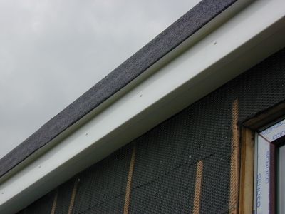
One of the big pains of converting the loft is keeping the whole lot reasonably watertight during the work. This involves lots of plastic sheets which waste loads of time fixing and unfixing every time you want access to the house to do some work. Hence once the dormer shell is up the race is on to get ready for the roof.
The first stage is the construction of the "warm deck" roof. This is simply 80mm thick sheets of cellotex laid directly over the firings on the roof joists with 3/4" shuttering ply placed on top. The whole lot then being screwed down firmly (with getting on for two hundred 5" screws!).
You can get pre made sheets with the insulation already bonded to "wood", but investigation revealed that the wood in question is usually something feeble like 6mm ply. It seemed this would allow too much movement of the roof surface (when walked on), which in turn could damage the roofing felt at the joints.
The next thing to do is prepare all the edges of the roof. This requires building "upstands" at the side and back of the slope of the roof (2" aris rail was recommended by the roofer for this).
Also before the felt can go on we need all the soffits and facias fitted.
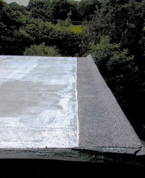
I wanted a good quality 3 layer felt finish, and did not fancy that job myself (I had yet to learn of the joys of "Torch On" felt which actually makes doing "pro level" flat roof work significantly easier!), so the final step is the easy one - sit back and watch the roofers do all the work!
Roof Done
So that was the roof complete, and all that remained was to bed on the ridge tiles to complete the transition between the flat roof and the front roof slope.
Windows
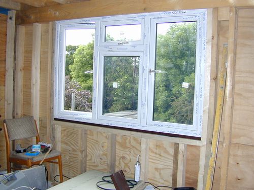
Now we could do the windows. I had a set of these made to order by a local (ish) firm to the requirements of the building regs in force at the time (see approved document part L). These windows are double glazed units with low emissivity Pilkington "K" glass, and a 20mm argon filled gap. They also have trickle vents for background airflow. The bedroom windows open wide enough to provide a suitable "means of escape" - again as per the building regulations that applied in 2004.
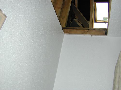
There was also a small window in the gable end wall near the top of the stairs.
Rendering
The rendering of the outside was one of those jobs that I had anticipated farming out to a specialist. However the various specialists consulted seemed keep coming up with quotes that were more than I wanted to pay (i.e. well into four figures!). Hence Trevor and I decided we would do it ourselves. Lots of sand and cement was procured from the local Wicks (their sand was half the price of the builders merchants!), a cement mixer borrowed from a neighbour, and I lots and lots of trips were made up a ladder with a 40kg bucket of muck!
Preparation
Before starting the rendering, we needed to get most of the lead flashing in place, since some of this will be partly rendered over. We also needed to get most of the uPVC facia and soffit boards up as well.
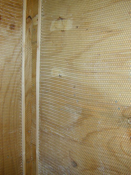
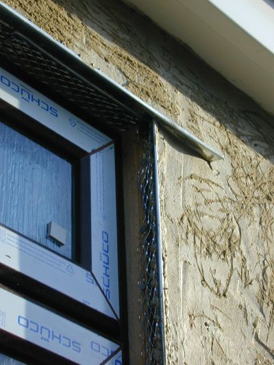
In order to render onto a surface like ply, you need to cover it with expanded metal lath. This not only gives a key the render can stick to, it also integrates into the render to act as a reinforcement.
The render goes on in two coats. The first is called the "scratch coat" (so called because once you are done putting it on, you scratch it all over so as to leave lots of indentations in the surface. This helps ensure there is a good key for the final top coat to bind to.
The scratch coat is about a half to three quarters of an inch thick, it basically covers the expanded metal mesh and makes up most of the thickness of the render. The top coat will take the final finish and is only a quarter to half inch thick.
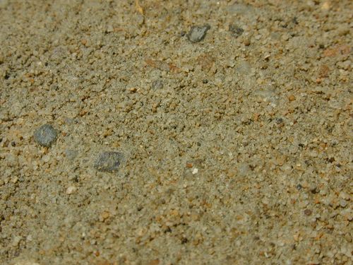
We used a mix of 5:1 sand to cement, and mixed our sand 50% soft (builders) sand, and 50% sharp sand. Some waterproof PVA was added to aid workability and add waterproofing to the final render. The mix of sands give a nice mix to work with, that is easy enough to apply, but should also be more durable and less liable to crack than using just soft sand alone. It is also a better match for the other rough cast render already on the house.
Metalwork
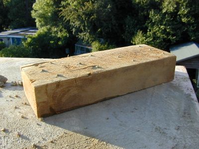
For what may seem like a "wet" trade, there is a surprising amount of metal required to do a good job of rendering something. This not only includes the EML described earlier, but also render "stops" - used to make a clean end or bottom to a section of render, also corner beads to give clean external corners.
Looks like Rain?
Not everything goes to plan, especially the weather!
Having just put the finishing touches to the last bit of render top coat or the rear of the dormer, we felt a few drops of rain... Never mind will be over soon we thought. Then it got heavier and heavier. In the end we retired inside for a break. What you see here is the result of a downpour, a wind blowing from the north (unusual in these parts), and no gutter yet fitted to the flat roof!
Render textures
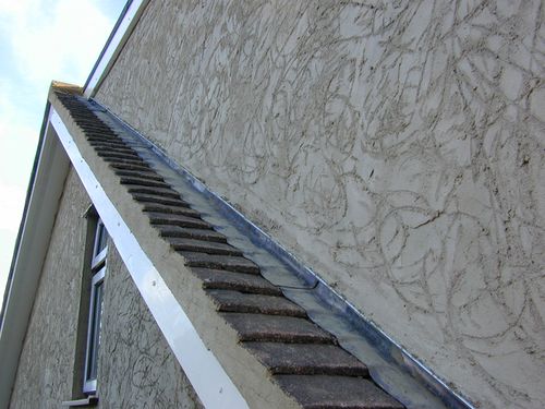
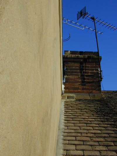
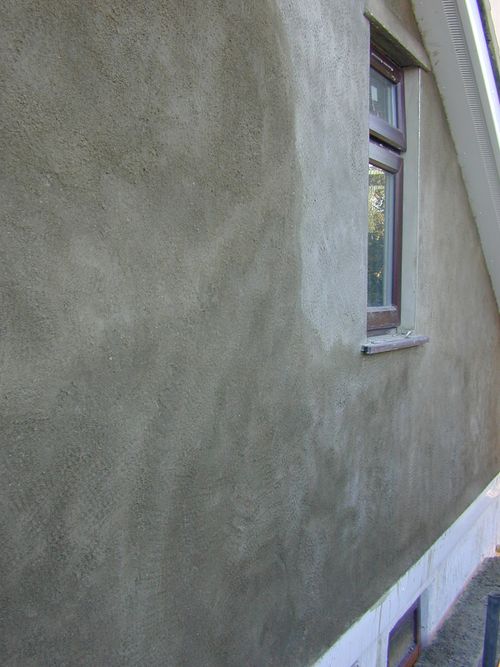
For the dormer cheeks, we went with a fairly smooth render. For the gable wall we used a much more heavily textured stipple finish since this was a much better match for the "roughcast" render already on the lower section of the wall.
Stairs
The most complex bit of joinery in the whole project is the staircase. Quotes to have these built seemed to be coming in at a about £800, but that did not include fitting (or any banisters etc). Hence I thought this would be a fun bit to have a stab at.
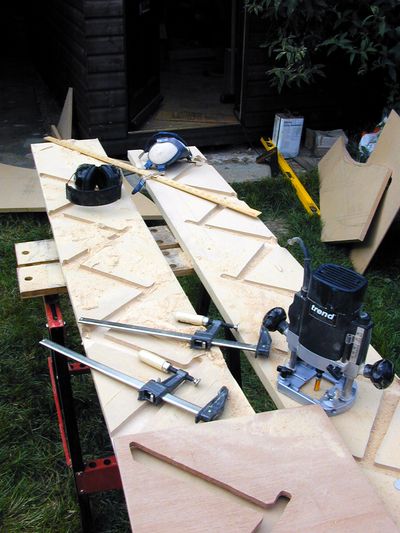
The first stage to making stairs is to work out how many you need and what size each should be. This the architect had already done. We spotted where he had measured/estimated the overall length (i.e. the "going") of the stairs and also the overall height (or "rise") incorrectly (which to be fair is almost impossible to do accurately until the ceiling is removed and the space made visible) and corrected for that. What we did not spot was his inability to count!
Fixing the error
Hence this was the first cockup of the project. Having built strings (i.e. the side bits of a staircase) to accommodate the steps as shown on the plans, and having set the rise of each step to be equal to the overall height divided by 12 (the number of rises specified on the plan) we found our new staircase was a whole step too tall! What we had not spotted until too late was the plan as drawn actually required 13 rises not 12.
Hence I set about producing new strings, this time with the big router (a Freud FT2000) using a template guide bush and a new template cut to allow for the offset of the guide bush. I also switched to 22mm thick PAR softwood which is a whole lot nicer to work with.
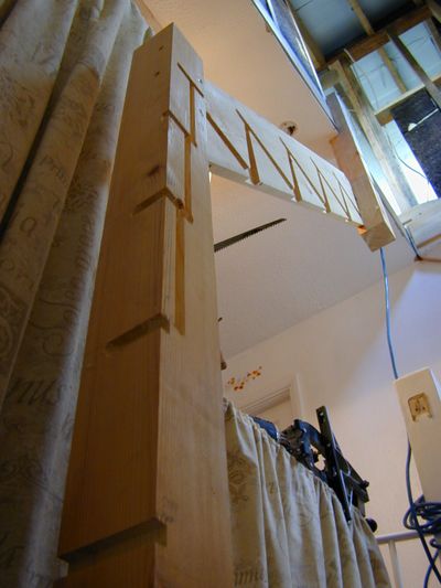
The mistake took the total materials bill for the structural bit of the stairs up to about £200 rather than the anticipated £150, but still a gave a saving over the cost of outsourcing this bit of the build. It was also a blessing in disguise since I much prefer the result achieved with softwood strings.
Installation
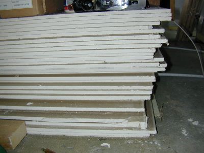
There was one "before you get started" job when installing the stairs. That was getting the plasterboard for the loft up into the space. We figured shifting fifty 8x4' sheets up two flights was going to be much easier without the second flight of stairs in the way, and before the top stairwell walls were in place.
So having had a stack of boards delivered onto the drive, we put one man in the loft with grippy gloves, and being the tall one, I got the ground floor short straw! We worked up a pattern were I would carry a board from the pile into the house, and poke it up the first stairwell resting about half way up the stairs. Repeat this until 10 boards were waiting.
Then grab a board, lift it up, and then thrust it above your head at arms length. The man in the loft then grabs that and halls it into the loft. Rinse and repeat until there is a big pile of boards in the loft!
The first job once the strings were done was to fix the outside, top and bottom sections to the wall. Lots of 4" screws will keep these firmly in place.
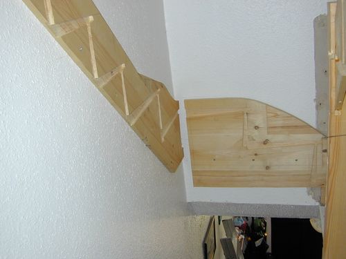
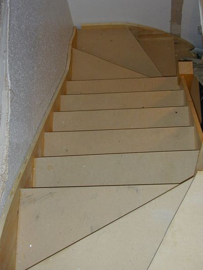
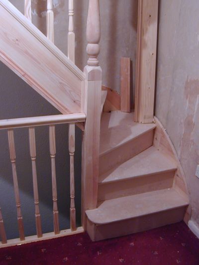
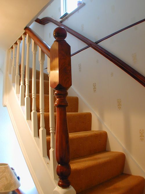
Since the staircase has to turn two corners (or have two quarter "winders" as they say), the string on the other end of the steps is actually quite short since many of the steps will need to fix to a newel post instead. Since the newels will need to be quite long it was simplest to make the base sections from 4x4" PAR softwood, but then fit nice turned posts to finish of the top section later.
Treads & Risers
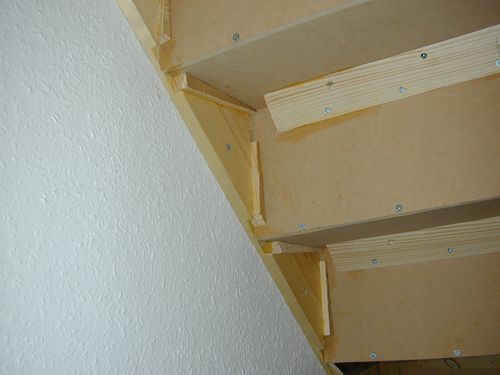
Once all the strings and newels are fixed, marked out, and all rebates are cut the treads and risers can now be fixed. These are glued and "wedged" into place with lots of softwood wedges which I cut on the table saw from spare bits of tile batten. Each of the step rebates tapers toward the front of each tread, and the top of each rise. The wedges are glued up and then hammered firmly into each rebate behind each step. This has the effect of making sure each step is very firmly jammed into each rebate with no ability to move, squeak, or rattle. The top of each rise also sits in a rebate in the underside of each tread with the base being screwed to the back of each riser. For good measure a section of aris rail is then glued and screwed to the back of each step. This helps maintain a very strong flight of steps since the design transfers the load placed onto any one step, on to several adjacent steps. The finishing touch is a section of softwood scotia moulding which is glued up and then air nailed to the underside of each nosing.
This gives the nose of each step a little more support and eliminates one more source of squeaks.
Banisiters
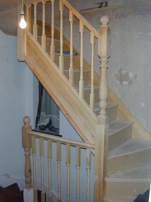
The final stage is to add the balustrading To make everything match all the existing banisters from the ground floor staircase were also ripped out and replaced with ones that match.
Three turned newel posts were installed. These simply plug into 2" wide holes drilled down into the newel post with an expansive bit. The "balls" then go on top in the same way (you could have "acorns" if preferred - they come separately).
The handrail is then tennoned into the newels, and the spindles cut and inserted. The spindles (pack of 30 from Screwfix) are glued and nailed in place at the base, and top. They are also held by small packing pieces that fit into the underside of the handrail rebate.
Insulation
Now we have easy access to the new space, we need to press on and get the rooms habitable. That means getting the insulation in, the plasterboard on and skim plastered.
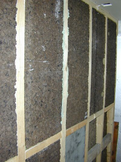
Anyone who has ventured into a loft in the middle of summer or winter will understand the huge range of temperatures that can be achieved in these places. To make them habitable we need to keep good control of both summer and winter temperatures. The answer here is ventilation, heating, and insulation.
You need to meet a minimum level of insulation performance to comply with the current building regs. While these requirements are slightly relaxed for loft conversions, they still result in the entire new story having a total heat loss figure of less than the existing living room just by itself!
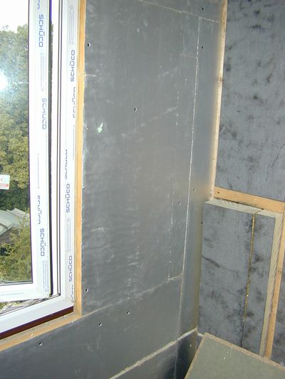
One way to get allot of insulation in a small space is with urethane foam or polyisocyanurate foam (PIR) boards (often known by their brand names like Celotex or Kingspan). This is a rigid foam panel that can be bought with foil covering on both sides. Even a little as 30mm of this stuff insulates better than a 9" thick solid brick wall!
It pays to shop around as well. What you see here was about £14 for a 8x4' sheet of 50mm thick foam. The local builder's merchant quoted £27 + VAT for the same thing! That would have added more than £1500 to the cost of the build!
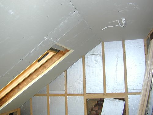
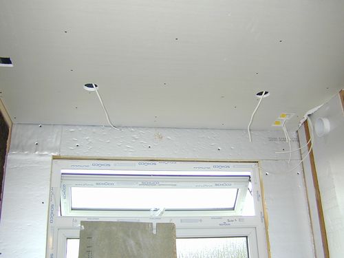
Any gaps in the insulation were filled with expanding foam. We also taped up all the joints in the foil faced panels with a self adhesive aluminium tape, to make sure we had a proper vapour barrier anywhere there was a risk of warm wet air getting through to cold exterior surfaces, or voided off parts of the building. This is to prevent any unwanted condensation forming.
Wiring
Before fixing all the plasterboard, this seemed like a good time to get all the wiring needed in place. While not strictly necessary, I took this chance to revamp the consumer unit end of things as well - upgrading the CUs, and RCD protection, putting in a proper Earth rod (TT Instalation), and splitting house circuits from garden and outbuilding circuits. Then I ran a new ring circuit to the loft for power, and a new lighting circuit. We also installed a dedicated smoke alarm circuit, with interlinked alarms on each storey.
To leave plenty of flexibility fo the loft rooms I added around 20 double sockets in total. This means that even if you end up covering sockets with furniture there are always others to hand.
While doing this I also took phone and data wiring to each room.
In the shower room, I ran in wiring for a humidistat controlled fan, a shaver light, and a electric feed for a dual fuel towel radiator, plus a transformer to power 4 low voltage flush mounted spotlights in the ceiling..
Flooring
Until now there was a temporary floor in place, but now we can start fitting out the rooms properly, it was time to lay the final T&G moisture resistant chipboard floor. This made it much nicer and safer to work anywhere in the loft
Plasterboard
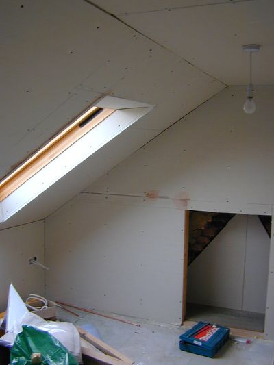
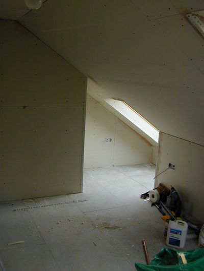
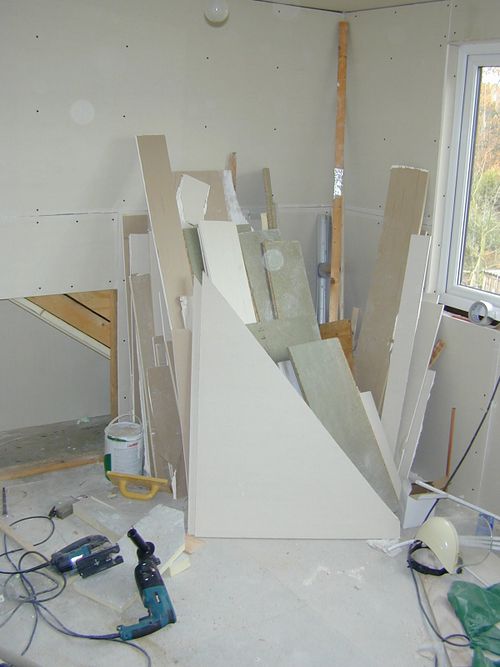
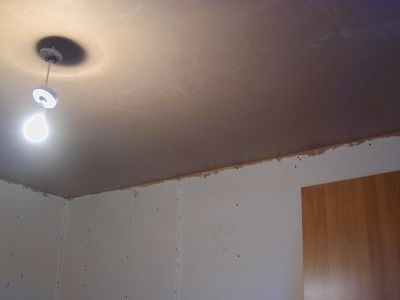
Plasterboarding was the next job. Nothing particularly interesting about this - lots of scoring and snapping, and then screwing boards to wall, ceilings, cupboard linings and anywhere else it looked like it needed it. Lots of dry lining boxes were installed for the wiring which was already in place.
Ceilings
I was working alone for the plasterboarding, so it made sense to get the hard bit out of the way first, so I started with the ceilings. To do this I knocked up a couple of Dead Man props from some spare tile batten. Fortunately the ceiling height was under 8' so it was relatively easy to lift a board above my head and then push it against the ceiling. I could then prop it with one hand, and position the dead man under it. Then nudge the board into the right place, and bend the prop more tightly into place. At this point the board was self supporting, and I could power drive in the dry wall screws.
Walls
Then repeat the process for the walls. The front sloping wall was the most difficult to hold in place before fixing due to the slope.
Once all the walls were done, then I moved to all the window reveals, and finally lining (and insulating) the cupboards (we had managed to find spaces to squeeze in more storage spaces by creating cupboards that used dead space between the existing chimney breasts).
Plastering
Time to master the lore of the gypsum! I was not looking forward to this bit given the reputation that plastering has for being "not as easy as it looks". Especially as I never used to think it looked that easy anyway! However needs must, and I have plenty of space to practice!
So we have a nice blank canvas to start work on, yards and yards of plasterboard...
So Raw Materials:
- Thistle Multifinish Plaster (buy it from somewhere that sells lots of it - you want it to be fresh, as fresh plaster remains workable for longer!)
- Water
Tools:
- Bucket
- trowel
- Hawk
- Corner trowels
- Large whisk like thing to go on the end of the drill!
Next, research: find all the descriptions you can of "how to skim plaster" and read them!
Last prep job was to tape all the joins with a adhesive glass fibre mesh tape to strengthen them and try to prevent cracking, and slap some bonding plaster into any gaps that are too large to skim over.
Micky Mouse guide...
So for skim plastering, you can do it in two coats or one coat. Most pros will normally go for two - especially if skimming over a "difficult" surface. Given that I was going to be very slow, and could afford the time to make good later with filling, sanding, and if required lining paper, I decided to go for the single coat approach. (also, nice virgin plasterboard!)
So my approach was:
Mixing: stick a few litres of water in the bottom of the bucket. Using the drill on a slow speed start whisking as you trowel in the plaster. Keep going until you get to something a bit like moderately stiff whipped cream! If you put a blob on your trowel it should just about stay put when you turn it upright.
Setup a "spot board" i.e. an offcut of plasterboard or ply on the workmate (damp it down a bit so it does not absorb too much water from the wet plaster), and tip the bucket onto it. If you have the mix about right it will just about avoid running off the board. Now go and wash out the bucket so it is spotless! Otherwise next time you see it you will find it has set! If you leave partially set plaster in your bucket it will also make the next mix go off too fast.
Scoop some plaster off the spot board onto the hawk with the trowel and practice scooping smaller amounts off the hawk back onto the trowel. Learning to tip the hawk toward the trowel in the same action helps!
First job, set about the ceiling, since any you splodge on the walls you can cover later ;-)
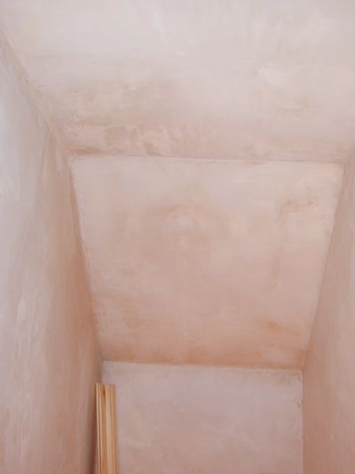
The trick here is to get it on, and not worry about getting it flat! Once it is up, smooth it out a bit and go away and start plastering a wall. Come back in 20 mins, after which time the plaster should have started to go off. You can now trowel it smoother. Wait some more, come back and repeat. You may need to splash some water on it now to get marks out of the finish. Keep fiddling about like this until it looks flat enough!
Now with a dollop of the stuff on the trowel, apply the edge of it to the bottom of the wall and wipe it up the wall. Hopefully it will stick. Keep slapping it on the walls until its all gone. Wait and repeat the polishing process as described above.
You will probably see pros using a large brush to splash on the water for final polishing. Personally I found a quick puff with a pump up garden sprayer was easier. These also come in very handy if you need to plaster over dry backing plaster or brickwork, since in these cases you need to give the wall a good soaking before you try to plaster it, otherwise the water will be sucked out of the plaster too quickly and make it unworkable.
Observations
This job is soooo much faster if you have someone else there to mix for you. That way you can keep working. Otherwise you keep having big non productive gaps waiting for the stuff to dry enough to polish, that are not enough time to do and apply the next mix. Hence this room took several days working on my own, when with help it could have been done in a few hours.
The frustrating thing is that by the time the whole job is finished you are starting to get reasonably good at it.. shame you did not start that way!
A word on trowels
Metal plastering trowels all look much the same. However the first rule is that you don't want to go plastering with a brand new one! Since it will be too flat, and have sharp edges and corners that will leave makes all over your finished plaster. What you need is a trowel that has been "broken in". This means the sharp corners are gone, and it will have acquired a slight curve over the short axis. The steel will also have acquired a bit more "spring" than it had when new and off the shelf.
There are a few ways to get a nice broken in trowel: one is to lend it to someone doing some rendering for a week. The more likely one is to go to work on it with a brick! Rub all the edges and corners against it to smooth them off. The shape you will only get from use, unless you buy a really nice Marshaltown "permashape" trowel. These really are nice and well worth the money in my opinion (about £35). They have a lovely smooth thin and light stainless steel blade, no sharp edges and are useable from new. Make sure you clean it well after use. If you have bought a cheap steel one it will rust and this can make it "drag" when used. A small cup brush on an angle grinder will see to the rust however.
Fitting out the shower room
I had a bit of a rethink about the layout of the shower room, since I did not think the one shown on the plan made best use of the space. By shifting the shower a little further toward the back of the house, there would be space to install a small airing cupboard beside it. This would also be a good place to make access to wiring and plumbing a bit easier.
Shower
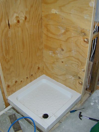
Since there are lots of bits of old ceiling joist under the floors, it is less easy to run drain pipes in the floor void. So I decided to build a small plinth for the shower tray - that way the waste could run above floor level along the wall and be neatly boxed in.
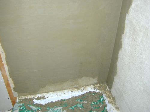
I also did not want to have plasterboard behind the tiles near the shower, since if there ever was a leak, PB tends to soak it up and then crumble. So I started with a lining of 19mm WBP shuttering ply, and then coated that in Expanded Metal Lath, before finally rendering it to give a hard and waterproof substrate to tile onto.
Tiling
(or "How to make a woman happy....")
Picture the scene, we are in a tile warehouse
"How about those ones with the fish?" (he says half joking).
"Oh yes! I do like those..."
Hmmm, rather expensive he thinks.
"What about those, they are not that different and half the price?"
"Well OK I suppose, I would rather have the fish, but you are right, those are OK and much cheaper"
"OK tile merchant, gimmy 13 square meters of those!" (gesticulating toward some nice blue tiles).
"Ah, says merchant, afraid it will be 5 weeks before we get those back in stock..."
"Oh Dear! What about those fishy ones then?"
"Er, let me check... Oh yes you can have them for next Monday"
"Oh, ok then, we will have those..."
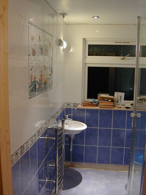
The Result
Not much to be said on this really. All the bare plasterboard had a coat of PVA a few days before as a waterproofing measure.
As you can probably tell I forgot to take many photos during the work!
Looked at the price of the tiles and decided that a nice electric tile saw was the order of the day (could not afford to break many!). Got the basic Plasplugs one. These are like a bench mounted angle grinder with a diamond disc sitting in a water bath! Very quick and easy to cut even fine shavings of a tile and they leave a nice smooth edge and don't make any dust. At about £32 pretty good value as well.
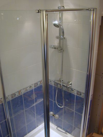
I used Nicobond waterproof adhesive and grout, and finished off with some Lithofin KF Grout Protector to keep it looking nice.
All the internal corners were "grouted" with silicone rather than grout so that any movement or shrinkage in in the new build would not crack the grout at the join.
Decorating
And so onto the home straight... (we will include laying carpets, and fittings curtains and blinds in this phase as well!)
External
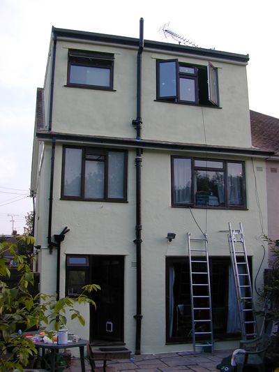
While not one of those "must do" jobs, getting the painting done does at least make the outside of the build look complete. It was also wise to get it done before the weather got too wet! The first stage of the painting was the dormer and the apex of the gable wall. These were done before the scaffold came down. In the case of the face of the dormer and the apex this was more a matter of convenience.
However, For the dormer cheek that faces the semi detached property, this was more of a necessity. Painting that in the future is going to be a little more tricky since it can only be done from the slope of the roof.
(with this in mind we replaced all the tile battens under this section of roof with new thicker ones!)
I bought two tins of paint, which in theory based on total area coverage ought to be enough for the whole house. In reality it turned out there were a couple of extra factors to include. Firstly new render sucks up paint far more than an already painted surface. Secondly we rendered a fair area with a stipple finish. So the actual area is far bigger than you think because of all the lumps and bumps in the finish.
Nett result was the whole house took four tins (20L) in total. Painting stipple is hard work. An ordinary masonry roller requires too much force to get into the crevices, and works out no quicker than a brush. The best tools turned out to be a narrow (4") "radiator" roller with a shaggy coat. And an emulsion brush with the bristles trimmed down to half length to make it much stiffer.
Interior
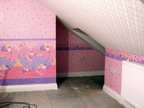
So after the bathroom was done, next order of business was the front bedroom and the new stairs.
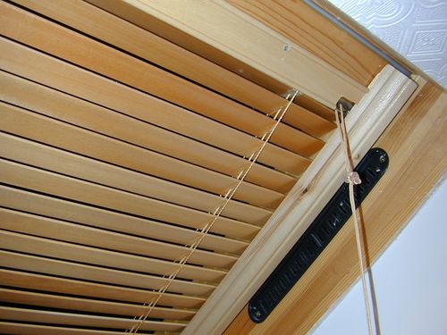
Next carpet, the underlay (Cloud 9 "Cirrus") was ordered from an online shop (half the price of the carpet shops). The carpet came from the excellent Kenbro carpet warehouse in Southend on Sea along with a fitter who was well clued up (not a job I like!). The colour is a beige with a pinky tinge.
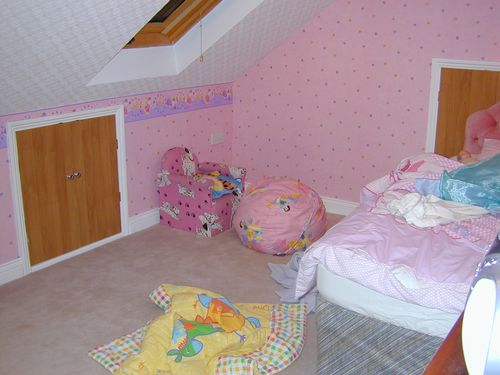
Slap in a bed, cuddly toys, books, and assorted stuff, and......
Ta Da!
Add small child, Primary object of whole exercise nearly met!
Clear remaining stuff out of vacated room, dismantle old bed, shift cot from our room to vacated room, add smaller and much much too loud child... and...
Really have met the objective this time! Arhhhhh peace, quiet. Sleep,
ZZZzzzzzZZzzzzz
Stairs
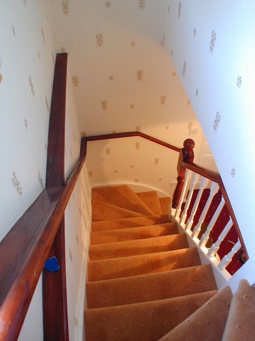
And going down:
Looking at the photos some years later, I realise that I don't actually have any of the back bedroom "finished" since that was not decorated and put into use until a couple of years after the main project was finshed. However that turned out to be a really nice double bedroom, with great views out over the countryside.
All Done
After many weeks of hard work, all the main building work was done. So the final visit from the BCO was arranged, and the completion certificate followed in the post a few days later.
Conclusions
| How long did it take | Hmmm, difficult to answer. We started work in April 2004, and had most of the structural building phase done by August. We lost a few weeks due to poor weather, and another week or two in delays getting materials. We had scaffolding for approx 13 weeks in total.
Progress slowed a little from then, and came to a complete stop as real work interrupted toward the end of 2004. Work resumed about April 2005, and by July 2005 all that remained was decorating and snagging. |
| What did it cost | About £10K for materials (and that includes carpets and decorations etc).
Fees of about £2,200, That's for the BCO, Architect, Roofer, and about five skips. The boiler replacement cost about £1,250 all in (including a few tools) Total spend on other tools and consumables is about £1,200 although they are not such a direct cost since I still have the tools! |
| Did it add value to the house | There used to be a time where conventional wizdom said that you would not recoup the cost of this sort of work on selling. Well conventional wizdom is not always right, and times (and property prices) have moved on!
In terms of financial return, the answer is also very probably yes, in that other similar local properties with similar conversions seem to fetch £40K - 60K more than the unconverted ones. (see hindsight section below!) |
| Unplanned changes / additions | I added some jobs along the way. Replacement of all the soffits, fascias, guttering being one of these activities. This probably added about £500 to the costs (included in the above). Although neighbours who have had this work done professionally have paid between £2K and £2.5K typically.
We went for a different shower room layout from that shown on the plans. This made better use of the space, and also added a small airing cupboard behind the shower. Not only is this handy in its own right, but it also makes for simpler access to pipes and wiring in the future if required. |
| Things I would have done different | Looking back, the main addition I think I should have made, would be the addition of a front dormer. This would have delayed the start of the project since planning permission would have been required, and it would have pushed costs up a little (but probably less than £2K). The benefit would have been a better proportioned front bedroom with more headroom. |
Observations
There are three clear advantages to doing this type of job yourself. It costs less, you get total control of the quality of the work, and you don't get your house invaded by builders.
The first one sounds simple enough. Judging by what friends have been paying for similar conversion work on their places (£30k - £45k being common), what we spent sounds significantly cheaper. However you ought to factor in time as well. Even if you were planning to do the job part time basis, there will be some periods where time is of the essence and you will need to work full time on the build (like when you have the roof off!). This probably only amounts to four weeks out of the whole project though. There is also a period of about four to six weeks worth of work where you will require more than one pair of hands.
Fringe benefits include getting fit, and a great sense of achievement.
The downside is obviously the time it takes and the commitment required. A team of builders would probably have had the work finished in 12 to 18 weeks (although you would probably still need to decorate it yourself!).
Should I try it?
The short answer is "that depends". To DIY this type conversion would have been very difficult if had I been constrained to a conventional 9 to 5 job (although you may manage with less ambitious conversion that is contained entirely within the envelope of the existing roof structure). You will need help for some of the work (better still if "help" has experience of this type of work). Personally I find having someone to work with, makes the job much more enjoyable than plodding along on your own all the time.
You need to enjoy taking on big projects. You will need confidence in your own abilities, and a "can do" attitude to learning new skills, while at the same time identifying which jobs you don't have the skill set to do (and don't have the time to learn, or future need for), or those which are going to be not economically feasible to DIY.
Finally be prepared for a few days of very hard work (getting 50 sheets (about 1.2 tonnes) of plasterboard up into the loft springs to mind).
With added hindsight
After a year or two, It can be instructive to look at what it is actually like to live with once all the dust has settled and normal family life resumes. The answer is: not bad in fact!
The design was such that the impact on the existing space was intended to be minimal with the only real change being the stairs. Since these were located in mostly "dead space" above the existing stairs, that change was small. Making sure the handrails were removable was handy since there was some loss of height available on the original stairs. This made getting furniture in and out a little more challenging - but generally no major problems.
The extra bathroom is very handy - even if it is two flights up!
The 35kW combi boiler could also just about cope with two showers at once.
An unexpected benefit of the new top floor was an overall improvement of the thermal performance of the whole building. All the extra insulation helping to keep it cooler in the summer and warmer in the winter.
Loss of storage space was unavoidable, but in reality we managed to make enough extra cupboard space, which along with the remaining eves space (and the access we created to the bonnet roof section at the front), meant it was still possible to find a space for all those carpet roll ends you don't want to throw out, and the other "stuff" that usually accumulates in lofts!
Having the top floor decoupled from the first floor ceiling was also a great benefit when small children are romping about above you! Along with a decent carpet underlay, the noise was reasonably well contained.
Changing requirements
One of the frustrations of "normal" life is that it is usually far from normal! So it came to pass for us. An unexpected change in family circumstance meant that in spite of all the careful design work and planning, our ideally converted house no longer fitted the new situation. Significant extra downstairs living space was required, and the extra bedrooms were not going to solve that one. So in 2008 we had to sell up, move a few miles down the road.
In some ways it is a shame to say goodbye to all the bits you could point at and say "I did that", but then again, one can also leave all the bits that did not work as well as you had hoped, and say "next time..."
It did however answer one question conclusively - and that was the one about adding value to the house. At the time we sold, prices had peaked and were already starting to slide, but even so we did manage to realise a price that represented the top end of what any comparable property in the area had sold for in the past.

